Chronicling my Long EZ construction (and a few other things).
Disclaimer
This blog is for entertainment purposes only, and is not meant to teach you how to build anything. The author is not responsible for any accident, injury, or loss that occurs as a result of reading this blog. Read this blog at your own risk.
I have finally reached the point where all the parts I’ve been making are going to be utilized. This of course required tearing down the old, hoping the new fits.
First one to go was the X axis lead-screw, and to do that the mill’s table had to be taken down.
Compare the lead-screw (left) to the ball-screw
After years of good service, this lead-screw is headed for the scrap pile.
Ball-nut stop block (left) vs screw-nut
The right end plate had to be drilled and tapped to accept the X axis motor mount.
Drilling...
... tapping...
... more drilling...
X motor mount added to the sliding table
The new ball-screw has a lot more usable “thread” than the old lead screw.
Ball-scew in place (ball-nut is backward)
At about this time things started not fitting right, and custom building began.
This corner had to go!
Sand belting action
A few frame modifications were also necessary
Adding clearance for the ball-screw
The Y axis lead-screw was discarded in favor of the short ball-screw.
Ball screw went in (left, with ball-nut backward again), lead-screw came out.
The original 2 holes for the Y spacer were tapped metric, so I drilled through them, and re-tapped them standard 1/4-20. I also added a third tapped hole.
Turning metric into standard
Y axis motor mount in place
In the end, the result was very nice. The fit and finish were great, and I cannot wait to add the electric motors.
Last time, I put all the pieces I machined together to show how they fit, however there was still one last internal component missing, the ball-nut with its stop-block.
The stop-block is threaded onto the ball-nut, but also attaches to the XY table, thus transferring the electric motor impulse into actual linear movement of the table.
I needed to make two of them, one for the X axis, and one for the Y axis, and they were slightly different from each other.
As usual I started with a piece of scrap aluminum, but this one was pretty mangled up, so I was happy to be able to recycle it into useful service.
Truly a piece of scrap metal
First order of business was squaring the roughly cut block of aluminum...
Facing one side
Aluminum blank
... and creating the step.
One "step" closer
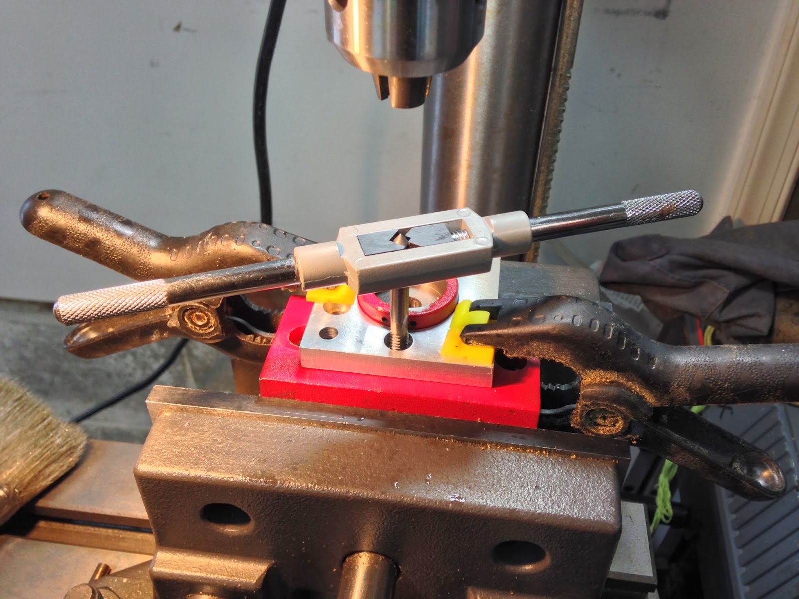
Then I went to work on the main hole. This needed to get drilled, bored, and tapped.
Beginning of the center hole
Enlarging the hole
The Mother of all taps!
Talking about taps, I bought this huge one on eBay, just to thread the two stop-block holes.
"TapZilla!"
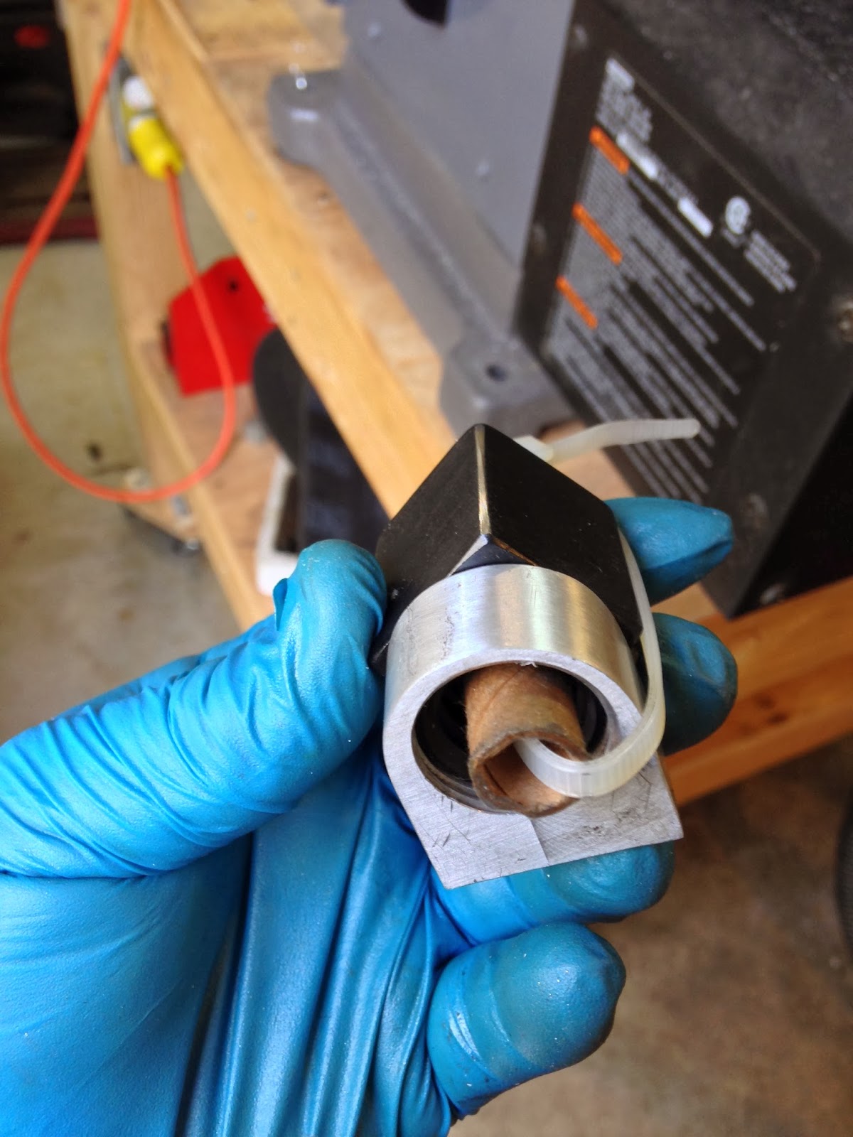
The last step was to drill and tap the small hole on the fat end of the block. Easy!
Small hole drilled...
... and tapped.
The last piece of the Y axis was finally done.
First stop-block done!
Stop-block in position
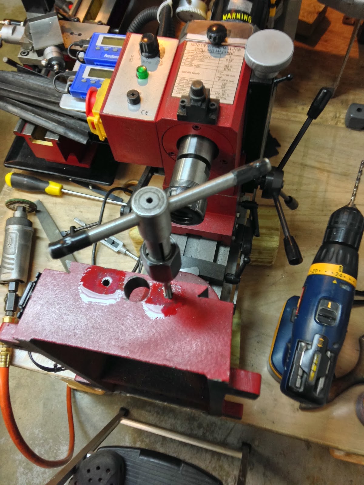
Time to start on the last stop-block...
Part "donor"
Using the band saw to cut the piece down to size
More facing
Taking a 0.150" (3.8 mm) roughing cut with a ¾" end mill
While the X axis motor mount gets attached directly to the right side of the moving table, the Y axis motor mount connects to a spacer block, which in turn connects to the front face of the moving table.
As always, the process started with a rough piece of metal that had to be cut down to its plan dimensions, and squared.
Raw material
Squaring one side
insert surfacing video
Finished stock
With the stock now in a usable form, I reproduced the bolt holes, and the ballscrew pass-through hole onto the part.
Locating the Y axis with an edge finder
Holes center-drilled
1/4" holes drilled all the way through
Reaming the ball-screw pass through hole
The spacer houses two sets of bearings whose purpose is to support and guide the ballscrew.
Ball bearing races
As you can imagine, the tolerances are getting much closer for the bearing surfaces, and a slow and methodical approach to their milling was necessary. I chose to use a boring bar held in a boring head to machine these countersunk surfaces.
Boring head set
The boring head is a fantastic tool, capable of high precision IF you know how to use it. I knew how, in theory, but the few times I had the opportunity to actually employ it, I was not very happy with the results.
However, I was eager and hopeful to experiment with different cutting surface angles, feed rates, and depths of cut, and this time around I got a lot better results, indicating that either my technique is indeed improving, or that I just lucked out. More boring practice will be required to settle this argument.
Finishing the bearing recess
Finished recess
Inner bearing surface
Ball bearing race
Outer bearing surface
This process had to be repeated on the back side as well, before the spacer could be considered done.
Finished Y axis spacer
I put all the parts I've made for the Y axis together, to give you a better idea of how they all fit.
Ball-screw with spacer and motor mount
Same thing as viewed by the stepper motor
Lead screw and hand wheel will be replaced by the ball-screw and stepper motor