Once I got to the point at which the main gear geometry had to be set, I ran into a snag with the fuselage stations (FS) numbering.
I felt like I was missing something important, or it might have just been a mistake at the source, one that never got corrected by a CP plans change.
Now, it is very possible that I am still overlooking something so, if you have already run into this problem and figured it out, please feel free to share. I’m just one guy, building on his own with minimal support, so all help is welcome.
Here are the details. Looking at page 9-1, the back of the wing spar is referred to as FS125.5 (125.5 inches from station 0), furthermore on this same page, the main gear axles location is calculated as being 15” in front of it at FS110.5 (125.5 - 15 = 110.5).
 |
| Construction manual page 9-1 |
Now, the back of the wing spar is butted to the front of the firewall, so the terms are interchangeable, as far as as the fuselage stations are concerned.
Looking at the back cover you can start to see a shift in fuselage stations, while the wheel axles are still at FS110.5, the firewall is now at FS125, hence the missing half inch. This would make the new distance from the axles to the firewall only 14.5”.
 |
| Rear cover of the construction manual |
There are a few more references to FS125 as the front face of the firewall. Here are four of them, one from the CPs, two from the construction manual, and one from the plans drawings.
 |
| CP#28 page 8 |
 |
| Construction manual page 7-2 |
 |
| Construction manual page 14-2 |
 |
Page A5 of the plans drawing
|
It would seem that the overwhelming evidence is for the rear of the wing spar to be located at FS125.0. This also means that the wheel axles are supposed to be at FS 110.0, if the 15” spacing is to be observed.
This makes the most sense to me, since I was confused by the single 125.5 fuselage station reference. Although probably not a big problem, I wanted to put it out there in case someone else was scratching his head over it.
As much as some of us builders idolize Burt Rutan, we sometimes forget that he is human like the rest of us, and an occasional typo is bound to go unnoticed, even in a document like the Long EZ plans, with over 30 years of close scrutiny.
UPDATE #1
A few hours after blogging this, and weeks since trying to figure it out, it finally hit me... Burt is not human!
A few hours after blogging this, and weeks since trying to figure it out, it finally hit me... Burt is not human!
Though he could have made things a little easier to understand.
The key to unraveling the mystery was right in front of my eyes all along, and ALL of the previous numbers from the plans were, and are in-fact correct.
How is it possible?
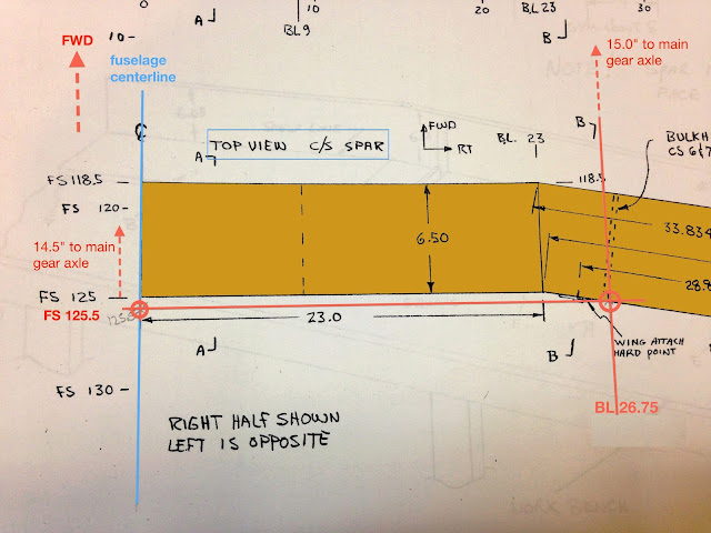
Allow me to explain... looking back at the text in page 9-1 it says that the 15” are measured from the back of the wing spar at BL26.75 (26.75" left/right of the fuselage centerline).
So far so good, but my previous statement, that the back of the wing spar and the front of the firewall share the same fuselage station, is correct only up to BL23.0, because further outboard the wing spar angles backward, and my statement is no longer correct.
Let's take another look at page 14-2...
As you can see, the back of the wing spar at BL26.75 is indeed at FS125.5, because it is past the wing spar bend, and it can be easily measured on the drawing itself, if you keep in mind the scaling factor.
The bottom line is, if you measure the gear position from BL26.75, the axles are 15” forward, while if you measure from the front of the firewall, the axles are only 14.5”. There was no missing 1/2" after all!
The weird thing is that the wing spar does not get built until chapter 14, while we are still working on chapter 9 here, so I’m not quite sure how one could have used the reference given, except by turning it into a measurement to be taken from the front of the firewall, a feature that actually is on the plane by chapter 9.
Anyway, “all’s well that ends well”, the mystery is solved once and for all, and hopefully I have beat this horse enough for one day.
UPDATE #2
Perhaps the modified drawing below might make it easier to understand how the 15" measurement is supposed to be taken...


EXCELLENT explanation Marco! Your OCD helped solve yet another Rutan mystery! These drawings are a great help in putting all the pieces together in one place. Thank you for saving me the headaches!
ReplyDelete