Chronicling my Long EZ construction (and a few other things).
Disclaimer
This blog is for entertainment purposes only, and is not meant to teach you how to build anything. The author is not responsible for any accident, injury, or loss that occurs as a result of reading this blog. Read this blog at your own risk.
Perhaps it shouldn’t be, but this chapter has always been a little intimidating for me, not only are the wings the biggest single item of this project, but they also need to work… or else. You know what I mean?!
Slightly foreboding, isn't it?
An issue that never previously crossed my mind has been the difficulty of maneuvering something so big and fragile around the shop. One soon runs out of space when working with so many wing pieces, and it always seems that anytime the foam is handled, more and more dents get added to the tally. So, reducing the number of interactions with the foam to those strictly necessary to the building process quickly became an imperative.
First things first though, time to get all the pieces of foam out of the many boxes they came in from Eureka CNC years ago, and put them together on the big table.
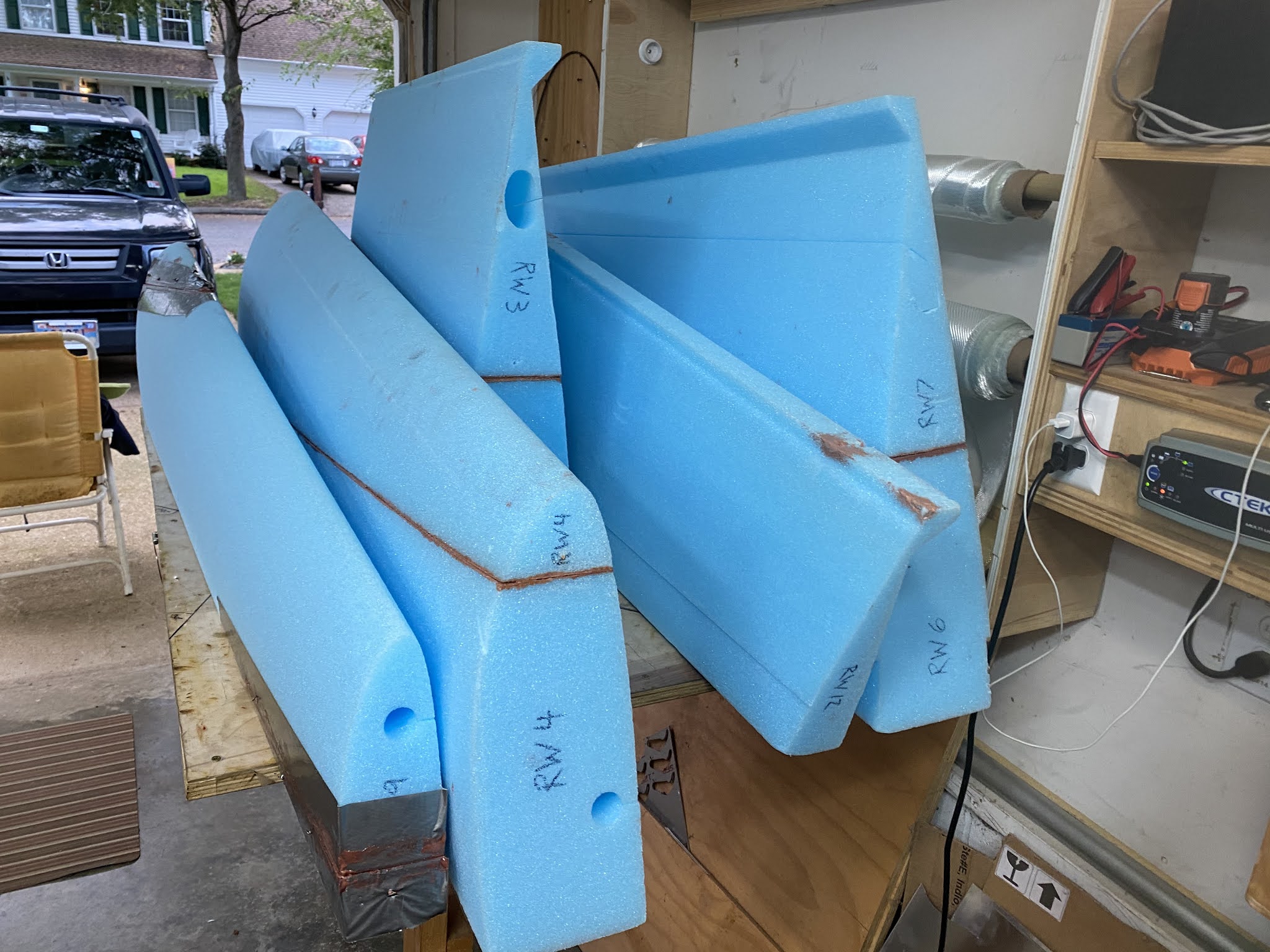
RW (Right Wing) foam pieces emerging from long term storage
OMG! This thing is humongous!
"What was that saying about how to eat an elephant?"
"Oh yeah... one piece at a time... gulp!"
The Long EZ plans only deal with five big pieces of foam, FC1 through FC5, but Eureka CNC cut the foam in thirteen pieces to make them easier and cheaper to ship, so it’s up to the builder to reduce these back to the five parts the plans describe.
Eureka CNC foam breakdown (plans' FC sections highlighted)
And reducing I did… for three days.
As usual, tape and slurry the joints.
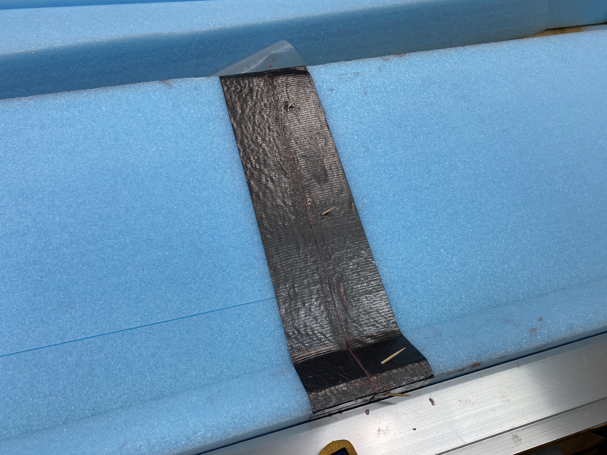
Tried non-reusable toothpicks instead of nails this time
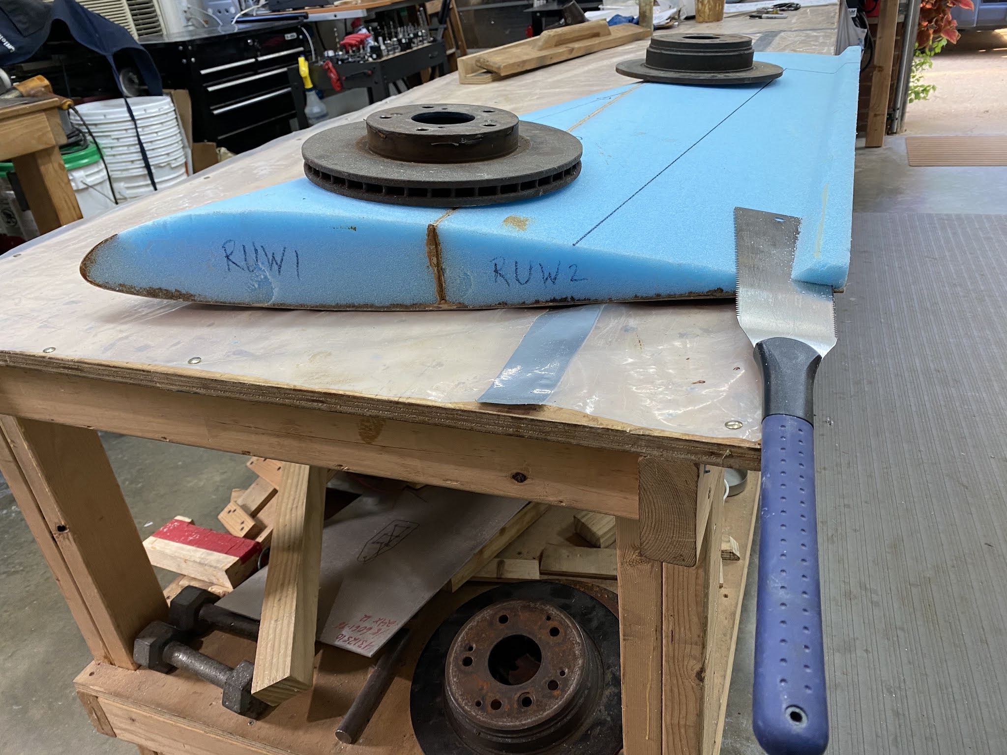
Honda Element rear disk brakes are very helpful during this process
Obligatory shot for future FAA observers, in case there is any doubt about who built this plane.
It's amazing how fast big surfaces gobble cups of micro-slurry
"Braking action report... Good!"
Rounded pieces are a bit trickier to weigh down
Using the same foam they were cut from helps immensely
The weighing down process becomes even more complicated
Using every trickery at my disposal to get the job done
Creativity and resourcefulness are very much part of the job description when building a Long EZ
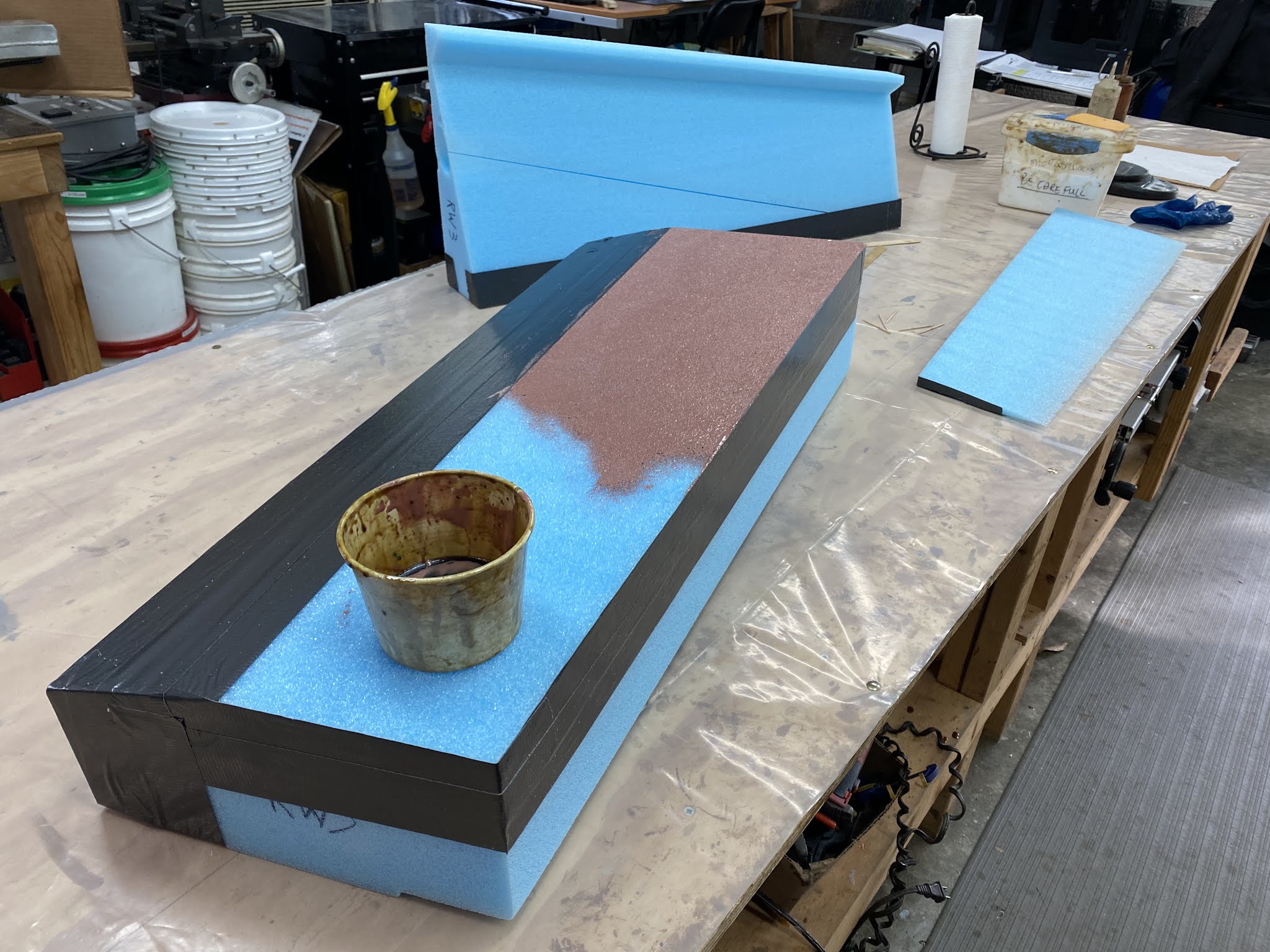
Micro-slurry to close the foam pores, and wet-micro as a bonding agent.
Had to use an extendable broom stick to reach both sides
Foam puzzle to weigh down the leading edge on one end...
... and a rear wedge piece on the other end, at the same time.
Admittedly I don't like to rush, and eventually I ended up with the five big foam pieces.
Wing pieces FC1 through FC5 ready for action
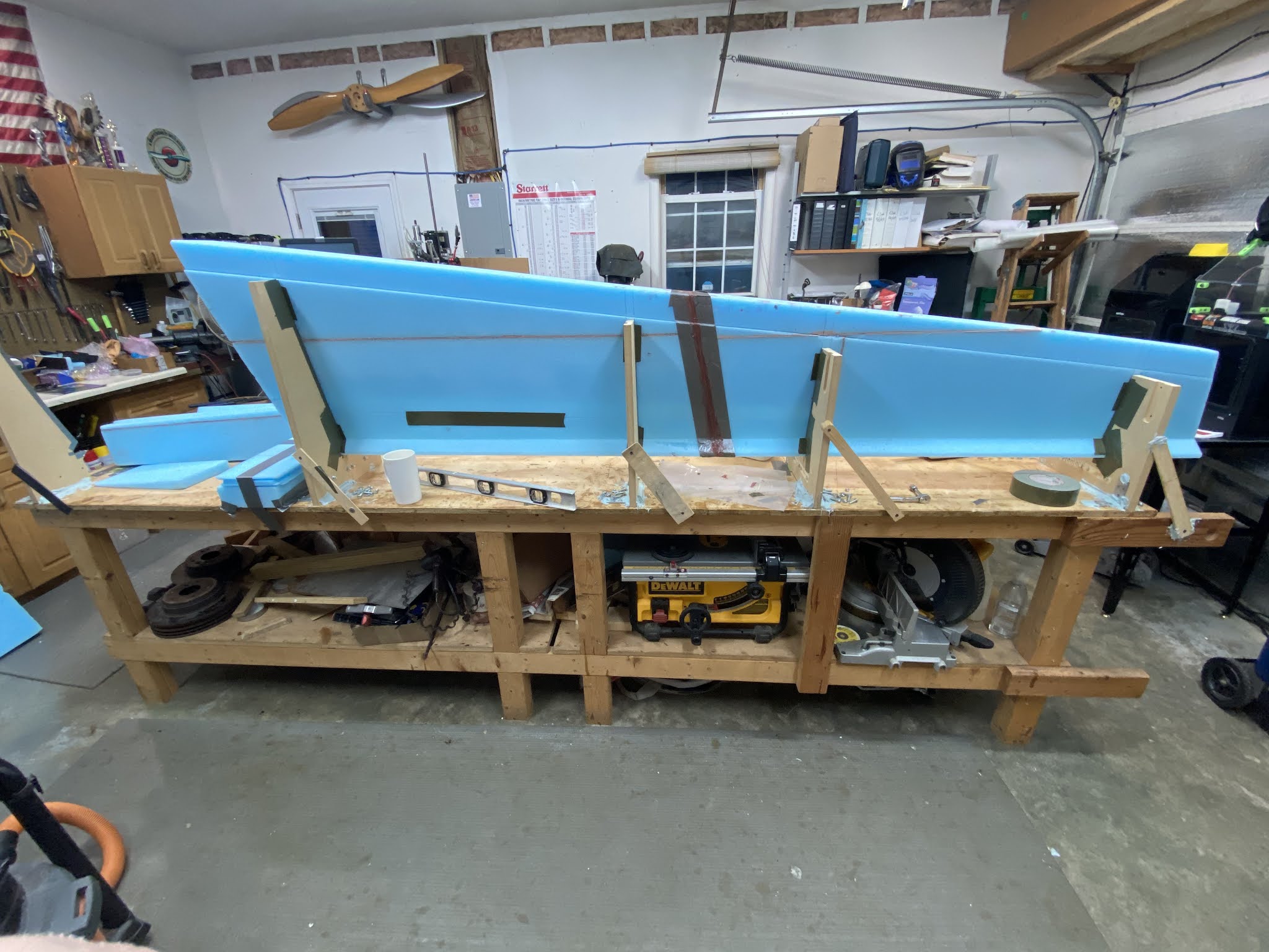
With all the foam blocks accounted for, and the help of my trusty laser, I set out to build the straightest wing jig I was capable of, little did I know it wouldn’t turn out to be that easy. Even though my twelve foot table is super flat, leveled in every which direction, and I would be using Eureka CNC cutouts, issues would crop up.
My first step was establishing a straight line 125.6” (3.2m) long that would represent the forward edge of the wing cutouts. Now, I don’t have a straight edge that long, and the sides of the plywood top that make the table were never square to begin with, so I turned on the laser and traced the red beam on the table.
Tracing the red laser line on the table
Dimensions are very specific on the plans
The plans specify the locations along this line for the wing cutouts, which are also marked with a common waterline allowing them to be lined up vertically.
A flat and level table is a God sent in a situation like this
All waterlines lined up on their own, thanks to the work we did on the table
Still no shimming required at this point
Four out of four here... scored!
This is what I look at when I align the cutouts vertically
Last cutout ended up needing a little help... Oh well!
I didn’t have to shim any of them until I got to the very last one.
Used hotel key cards to shim the cutout up. I reckon 4 out of 5 is still pretty good.
At this point I tried inserting the foam pieces into the cutouts, only to find out that that didn’t work, further damaging the foam. I ended up needing to disassemble all the cutouts in order to insert the foam, but I had already Bondo’ed the aft pieces in place, so I had to chisel that off. Note to self: don't repeat this mistake on the other wing.
Did not like having to do this
Had to chisel off all the back pieces
With that, the wing went in.
Finally an operational jig
Crap! This thing looks even bigger now.
After a few minutes of contemplating what had I gotten myself into, I started noticing a few issues.
"What's happening here!?"
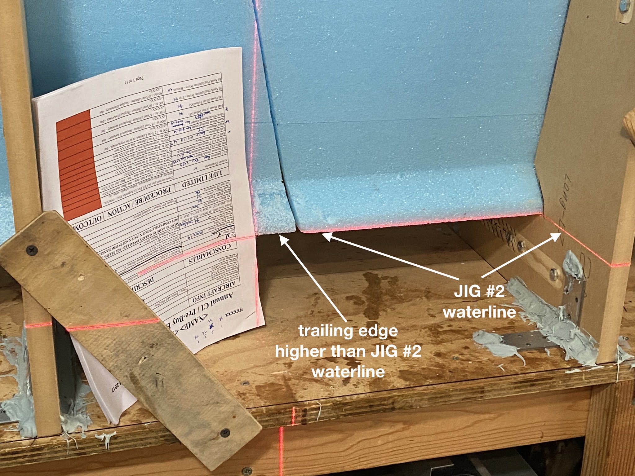
The more I looked at it, the more it looked like cutout #2 (second from the right) was too low, and that if I shimmed it up everything might fall back into place.
Measure with a laser and cut with an axe type of thing.
Now, I had to make an executive decision. I could either keep my “straight jig” and build a crooked wing, or adjust jig #2 and end up with a straight wing.
Duh!
Shimming jig #2 up brought the trailing edges back in line…
Cutout #2 waterline offset up
Now that's more like it!
… and the spar-cap trough…
Much better
… and the leading edge…
Checkmate!
Yeah… I’ll keep that!
Marked the new waterline for when I build the left wing
In addition to raising jig #2, it had to be pushed back about ⅛" (3mm) from the black reference line in order for the wing surfaces to match without a step.
Jig#2 backed off the reference line
This will be a problem again later on when both wing and jig are flipped 90º on that side.
Meanwhile, let’s bond the two bottom pieces before they move again.
FC2 and FC3 taped before bonding
A high level view of the job at hand
Foam bonded the same way as previously done with the smaller pieces
Used removable nails to prevent the foam from shifting overnight
Bonded the foam to the jig, top surface only, per plans.
Cleanup the next day
Next time we will be creating the wing root pocket on the first foam block (FC1), and begin installing the wing bolts mounting plates.
With the issue of the plans' error behind me, and the foam cores already glued together, it was finally time to get dirty again.
First though, I would bond the cores to the table to prevent any twist from happening during the curing process. I used a couple of foam blocks and a straight 2x4 screwed to my table to construct a pretty sturdy foundation.
Using the foam the winglet was cut from as a base for glassing
Foam duct-taped over up for the front, and a straight 2x4 to support the trailing edge.
Weighing everything down while the 5 minute epoxy cures
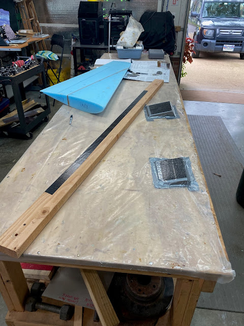
The fiberglass layup schedule for the winglet is pretty straight forward. Two UNI plies corner to corner crossing each other, plus an additional BID ply in a 14” x 18” area where it will later connect to the main wing.
Layup schedule for both sides of the winglets
I started with the right winglet first.
I accidentally cut from the wrong roll (BID vs UNI) so all this glass was later chucked
After starting over, I laid the two crossing plies of UNI over the winglet.
Made sure the final BID ply didn't cover the custom sized rudder
Peel-plied the whole thing
The next morning it was time for cleaning up, which as usual took all day.
The plans have you trim the glass right at the leading edge apex
I like to roll the glass over the other side an inch or so even though cleanup is harder
I like having 4 plies instead of 2 at the very leading edge should I ever hit anything
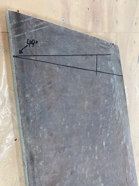
I also decided to cut the winglet down to size at 49” along the foam trailing edge.
Winglet sanded
The 49" is still one inch long, but I'll trim that after mounting it to the wing.
Used the Japanese saw for this job
Easy peasy
You might remember from my last post that the winglet is only 48” along the foam, plus a one inch urethane foam cap.
Original winglet plans
So, why did I do it this way?
You see, step #2 of the plans has you add the 1” urethane foam cap, and step #3 has you measure the distance from the aileron inner forward corner (WPRP) to the rear tip of the winglet (measurement C in the picture below).
Measurement "C" (118.35") is taken from the top of the urethane winglet's cap (48" + 1")
Since the 1” urethane foam cap gets installed before the C measurement is taken, and because I would like to do a backward sweeping top cap to the winglet, I chose to cut the winglet one inch long, as if the regular urethane top cap was already installed. This is only for the measuring purposes during winglet installation of course. Once the winglets are mounted to the wings, I will cut the top one inch, and install a more artistic 1” inch tall top cap.
James Redmond's beautiful Berkut
Next, I took care of adding micro to the trailing edge. This is normally done while fiberglassing, but I decided to peel-ply it instead, and take care of it at a later time, when the trailing edge is stiffer and more able to resist my pressing on it.
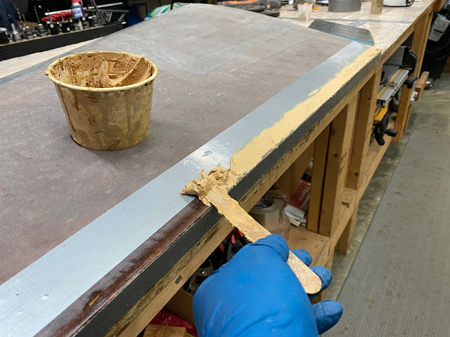
Trailing edge taped with pure epoxy applied
Adding dry-micro to the trailing edge's juggle
With peel-ply over the dry-micro
A day later I ripped the peel-ply off and sanded the micro smooth. That’s when I noticed the gap.
This got me stumped
I couldn’t understand this since I thought the addition of this micro was meant to create a smooth transition back there.
Did I screw up fiberglassing?
I checked the original shape of the left winglet trailing edge foam, and found the same problem.
Checking the foam on the left winglet
This one has a gap too
This was getting weird.
Did Eureka CNC screw up hot wiring the foam?
I dug up the plans for a closer look, and this is what I found…
I'll be damned! The plans have a gap as well.
I guess nobody screwed up.
I felt much relief that I hadn’t caused the problem, but now I totally questioned the rationale behind the technique. Putting micro on the trailing edge during glassing (or afterward in my case) does not even come close to filling the gap in the trailing edge area, and so it doesn't save any future finishing work, rather it adds another step to an already long day.
I resolved to skip the micro trick from now on (it is not actually called for in the plans anyway), and with that in mind I moved on to the left winglet.
Reused the same 2x4 and foam blocks to support the other winglet
Filling in all the major foam imperfection with dry-micro
Using UNI right off the bat this time 😄
Ply #2 down. Didn't catch a photo of the smaller BID ply
Unfortunately I ran out of the sheet peel-ply, and made do with a roll of the smaller 3" (8 cm) kind.
Sometimes the lack of proper planning creates the need to improvise
This worked well, but the next day it proved to be worse at cleanup time. Ripping the peel-ply off left a bunch of strands on the surface, and there was a small ridge of epoxy where any two plies overlapped, requiring quite a bit of sanding.
This should teach me to plan ahead next time
Transitioning the 2 plies to the bare foam smoothly takes time
With cleanup completed, I cut the left winglet to 49” also.
Trying the vibration cutter this time
The outer surface of both winglets was now done.
Looking sharp
Better finish these guys before the foam gets any more dents in it
I moved to the inner curved surfaces next. First order of the day was removing the fishtail and the peel-ply embedded in the trailing edge, including the staples that held it to the foam during glassing.
Cutting off the excess foam (aka fishtail)
You can see the staples sticking out of the foam
Ripping the trailing edge peel ply
"Now, that's a clean trailing edge!"
Like with the canard, the winglets are used to house antennas internally, where they do not contribute to the overall drag of the plane. So, while the canard was perfect for hiding the horizontally polarized NAV antennas, the winglets are ideal for the vertically polarized COM antennas, once again leveraging the radio transparency of fiberglass structures to our aerodynamic advantage.
First though, I had to make them.
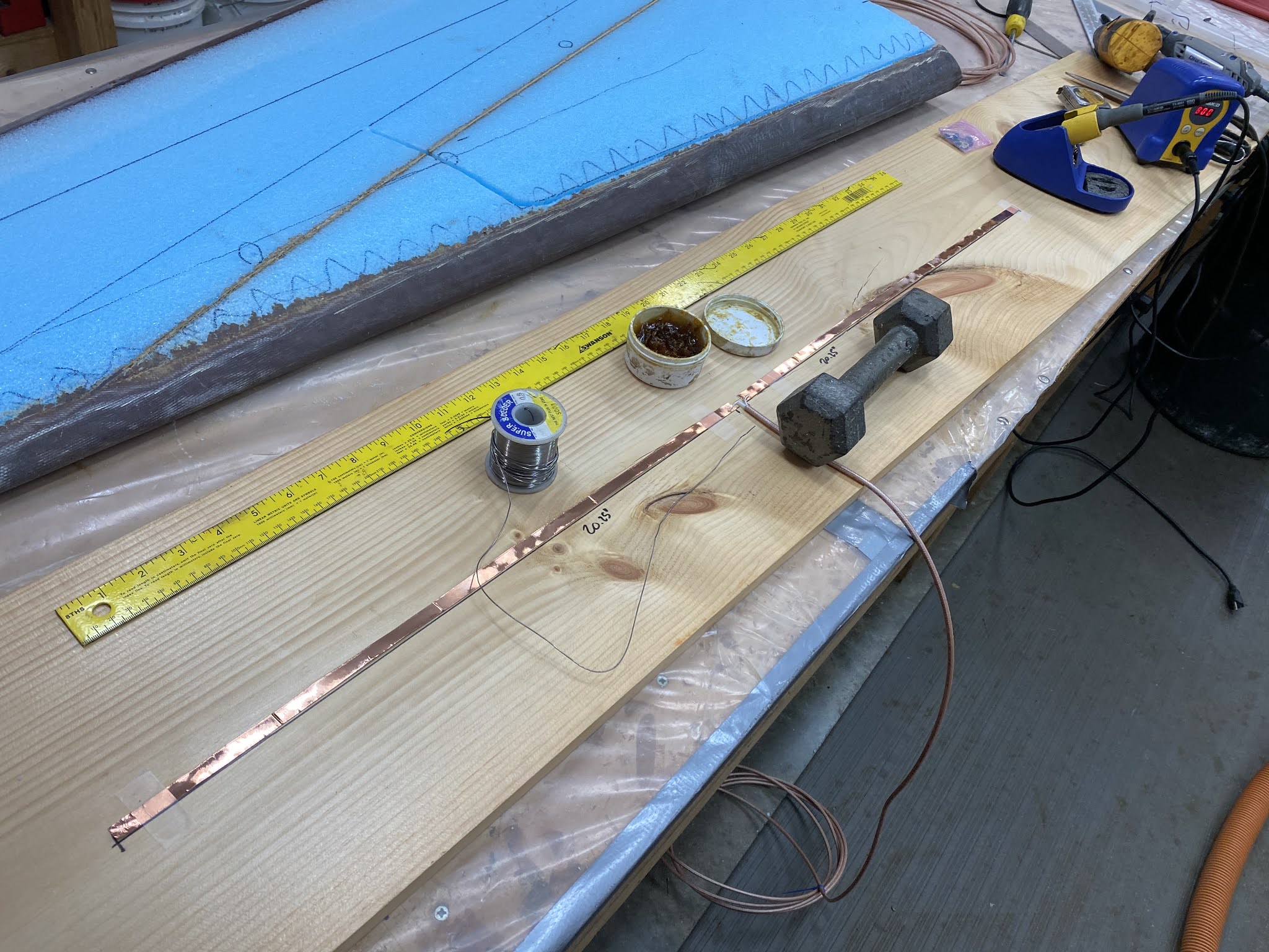
How the Com antennas are made
Antennas bits and tools
RG400 coax cable stripped and ready for use
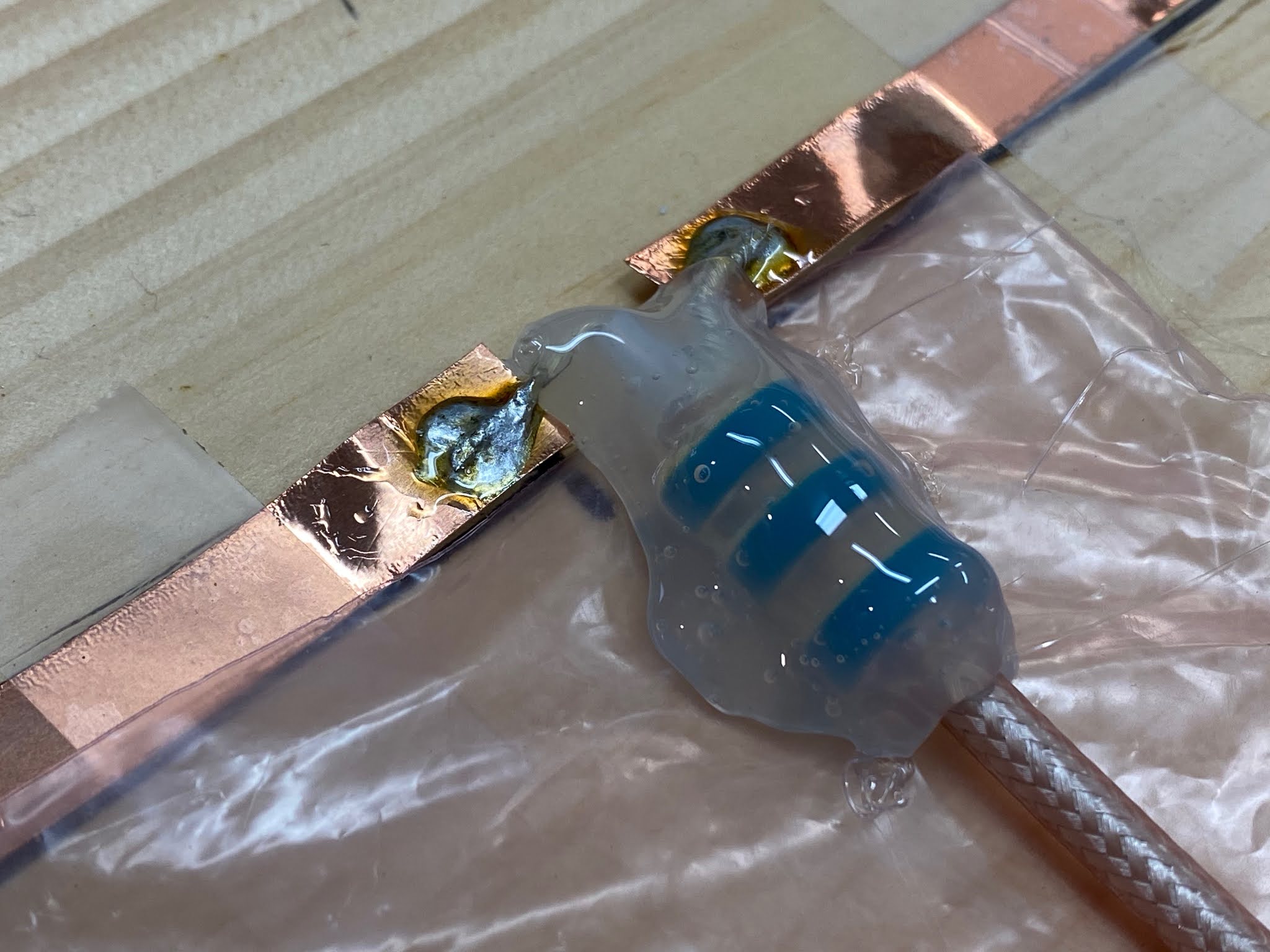
Coax soldered to antenna dipole
Baluns prevent reflected transmission energy from traveling back to the radio
Using hot glue to fix the baluns position on the coax cable
These antennas are very delicate, and easy to damage as you’ll see shortly. The good news is they can be repaired almost as easily.
Antenna location plan
Cutting a trench for the coax cable
Made the trench narrower than the cable so that the foam would hold the coax down
Coax exit point
All parts in place
Left enough loose coax to go through the entire wing and emerge at the center section spar
I modified both winglets in this way in order to have two COM radios down the road, same as JT now has.
Com#1 and Com #2 antennas are in place
With the antennas mounted, and continuity verified, I moved to glassing the left winglet.
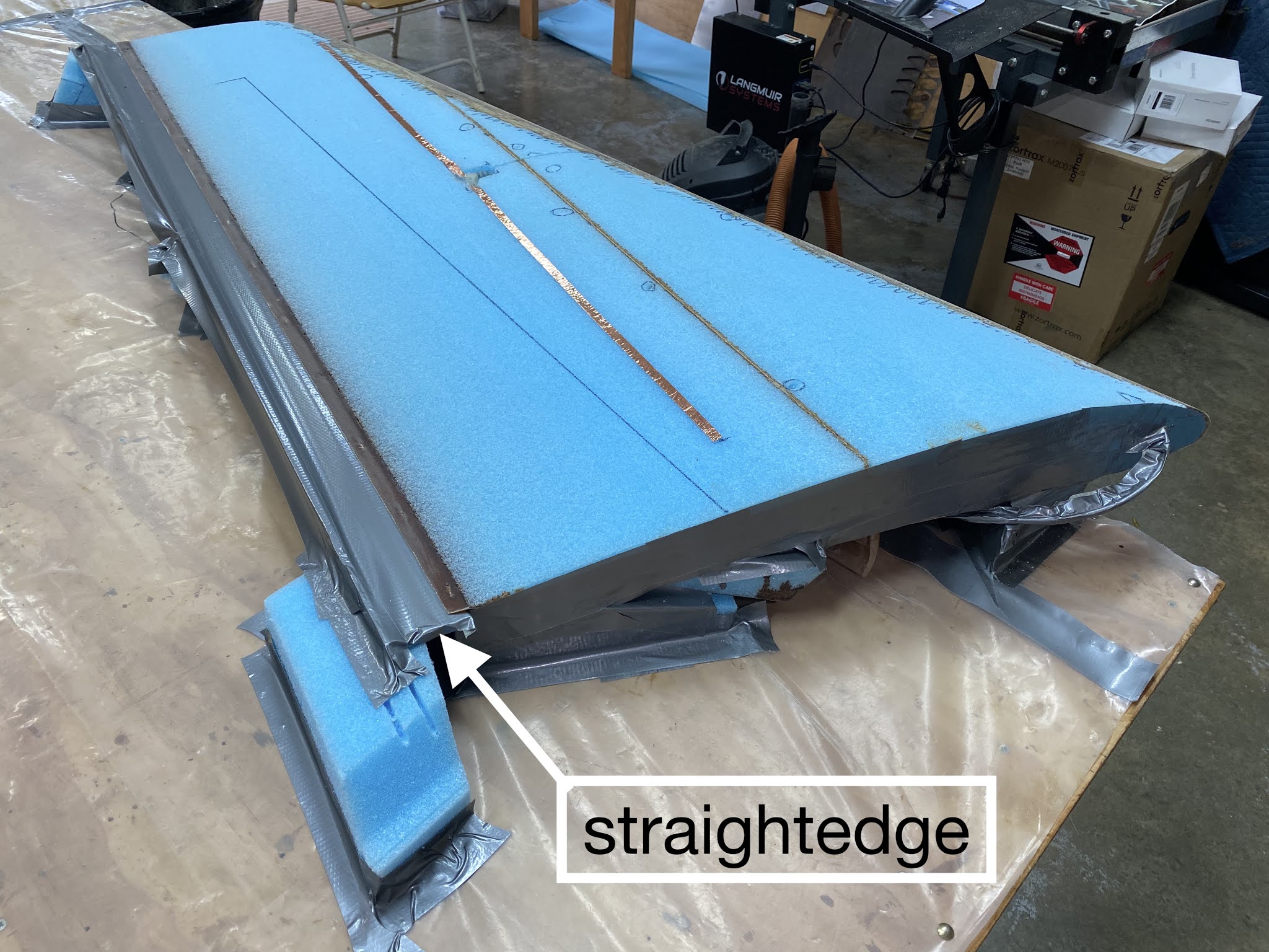
Once again I wrapped a long straightedge with duct tape, and used it to support the trailing edge, just in case. I also raised the entire winglet off the table and over the edge in order to be able to glass the leading edge overlap more easily.
Not taking any chances with the straightness of the trailing edge
Hanging the leading edge over the table edge to ease glassing the overlap
Before any glassing could be done though, I had to fill various holes, and the coax cable trench I cut earlier. Dry-micro always worked well for small holes, but filling the trench used up a lot of it, and although I worked very hard to reestablish the winglet contour, I was never able do it to my satisfaction.
This means that the fiberglass would turn out slightly flat over the trench, and the proper rounded contour would have to be achieved only at finishing time. Quite alright, but not ideal.
Dry-micro over the big depressions
Micro-slurry over the foam
First ply on. Not too happy about the dry micro sag in the coax trench.
Another shot to show the coax exit pocket unevenness
Ply #2 going on
BID patch added where the winglet will attach to the wing
Got more peel-ply sheet in
I spent the whole next day cleaning up.
This looks a lot better than when I used the 3" wide peel-ply
The outer facing side of the winglet is going to need some cleanup at both ends
This overlap is going to take time to blend in
First though, we need to cut the extra material
The trailing edge needs to be reestablished using the straight edge and a cutting tool
Excess fiberglass trimmed off the rear of the winglet
That's a good looking trailing edge
Wouldn't want to run into this edge
Glad to see the trailing edge coming out this straight
The left winglet difficulties I encountered inspired me to try something else on the right winglet. I purchased pour-foam to fill the coax trench and any other depression, instead of having to rely on dry-micro again.
The two part foam expands rather quickly to thirty times its original volume, so a little goes a long way. This stuff is also super tacky, and it sticks to everything, to the point that mixing sticks, cups, and anything else used cannot be reused. It also dries quickly, and subsequent pours can be made after just ten minutes.
To make sure I wouldn’t run into any issues, I went above and beyond to protect the winglet from this stuff.
Setting up the right winglet. Note the straight edge under the trailing edge.
Creating a dam for the X-30 foam test pour
My first time using it did not go so well. I should have mixed a little more than I did, making the foam a little denser, instead of trying to spread the little amount I had over a large space. I resolved to use more next time, and fill the voids later with a bit of dry-micro.
I must have overestimated the pour-foam expansion
Unfortunately, while removing the tape that was holding it down, I broke the antenna.
Removing the winglet protective layers ended up ripping the fragile antenna foil
Luckily, fixing it was a quick and easy job.
After trimming the pour-foam down, and getting the roll of copper foil back out.
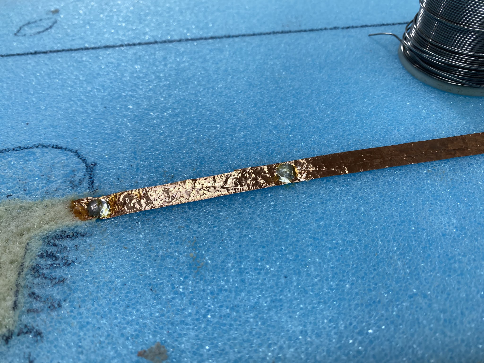
New copper foil spliced in and tested
Detail of the soldered splice
Another continuity check revealed no further problems, and I decided to give the pour-foam another shot at a couple more low spots.
Trying the pour-foam again
Got a nice build up this time
Both spots cut and sanded back to proper height and shape
This worked quite well at reestablishing the curved contour, so I decided to give it another try in another area that was still slightly low.
I am getting hooked on pour-foam now
"This is fun!"
"Loaf of bread anyone?!"
It cut and sanded perfectly, and the proper airfoil profile was easily reestablished.
This technique was easier to use and worked much better than the dry-micro
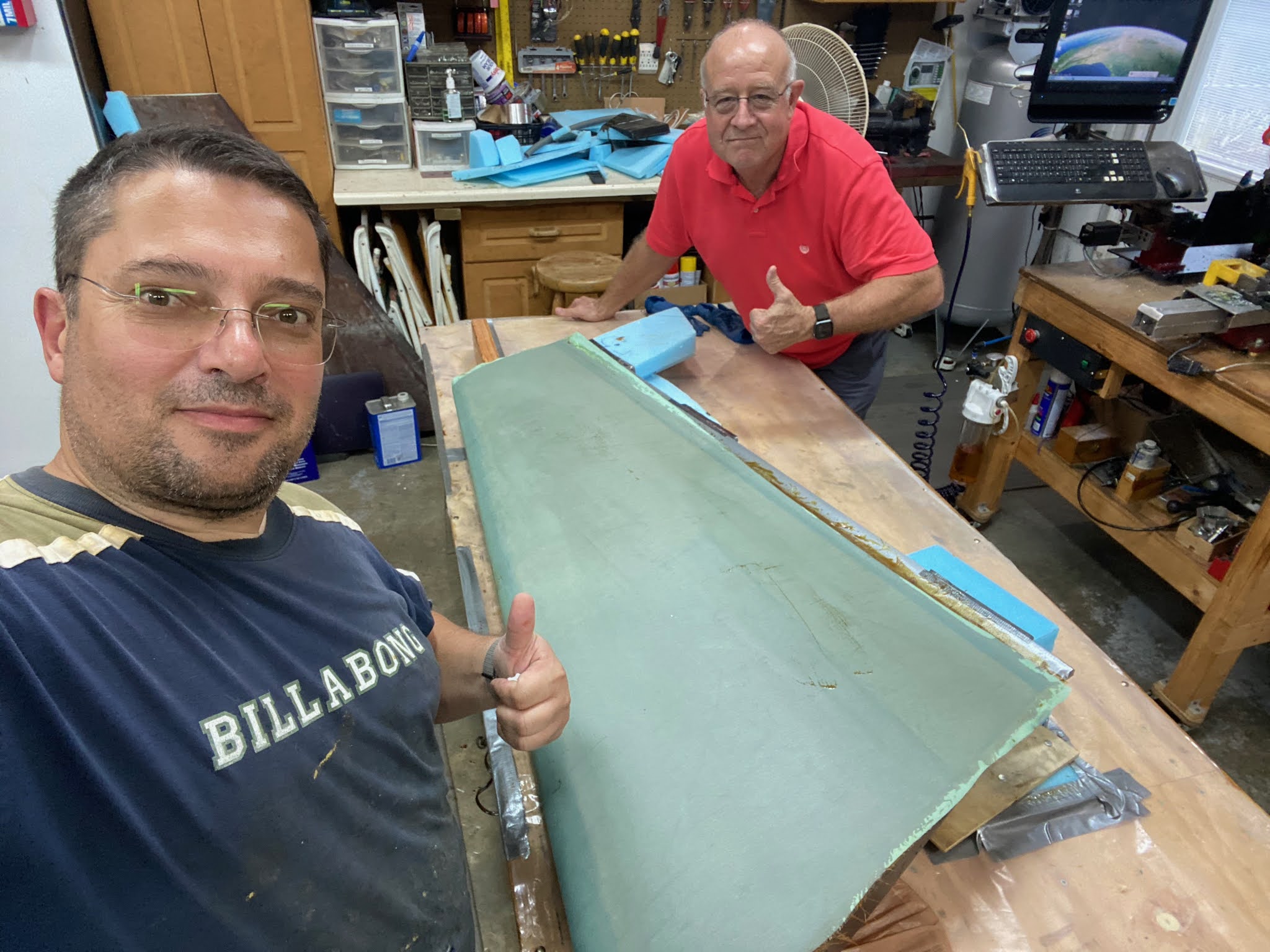
The only thing left to do now was glassing, and for the first time in a long time I had a helper.
I don't always accept apprentices, but when I do they must have impeccable resumé.
Now that Chris owns a flying LongEZ, he could benefit from some hands-on experience fiberglassing airplane parts. So this ended up working well for everyone, Gina caught a break, I got some help, and Chris practiced fiberglassing on a much larger scale than one gets at an EAA workshop.
Getting started with the UNI
I'm gonna make a builder out of this fly-boy
The session went well, and was a lot shorter than my previous ones. Chris was satisfied enough that we might see him slinging epoxy again on this blog.
Unfortunately he was nowhere to be seen the next two days, when the cleanup took place 😂.
Blending the overlap to the rest of the winglet
As slow as I am when building, cleanup is an even slower process for me, and I just couldn’t ask anyone to endure something I myself wish I didn’t have to do. More importantly though, it is relatively easy to damage the underlying structure if one is not careful with the precision sanding required at times, and since I am the guy who is going to be in the front seat of this plane one day, I feel it is my responsibility to perform this important and delicate task.