Disclaimer

This blog is for entertainment purposes only, and is not meant to teach you how to build anything. The author is not responsible for any accident, injury, or loss that occurs as a result of reading this blog. Read this blog at your own risk.

Friday, February 28, 2020

Ch 22 - Electrical/Avionics - Part 21

Panel #5 - design
  
“Come on, you should have seen this coming!”

Really, panel #5 was already being lusted over as I was cutting #4 on the CNC plasma table.

This is not going to be a new design but an incremental improvement to the old concept, and will still allow the panel to be removed as a whole, and brought home for further tinkering.

The first thing you should know about the old panel is that it has been performing very well, and has logged quite a bit of IMC, as well as a few actual instrument approaches, and if you made it to Sun & Fun 2019 you would know that getting out of there and making it home would not have happened any other way.


Leaving S&F 2019 required an IFR clearance since most of Florida, Georgia, and South Carolina were socked in tight.

At this point I could have just been happily flying about (and I have), but there is just one more thing that I wanted to incorporate into the panel… a COM2.

Although there are many reasons why that is a worthy addition, let’s just say it helps lower your workload during IFR operations by allowing you to remain on Center frequency with COM1 while checking the ATIS/AWOS (weather) simultaneously on COM2, it is also a great backup in case  of COM1 failure, turning an emergency situation requiring priority handling from ATC (read unpleasant paperwork), into a non event.

Problem is that you cannot just have two radios without a way of switching between them, so adding a second radio would necessarily require adding an Audio Panel as well.

Next thing you know, this past Christmas Santa brought JT a new Trig remote radio and a Trig audio panel. I know, JT is such a lucky girl. I wish I had gotten something that nice for Christmas ðŸ˜‰.


Trig remote radio TY-91

Trig audio panel TMA45

Needless to say, the upgrade would require a complete redo of the panel, its backplate, and the wiring, So, I spent most of January and February figuring things out, and that required a few email exchanges with the Trig folks which by the way have been delightful to work with.

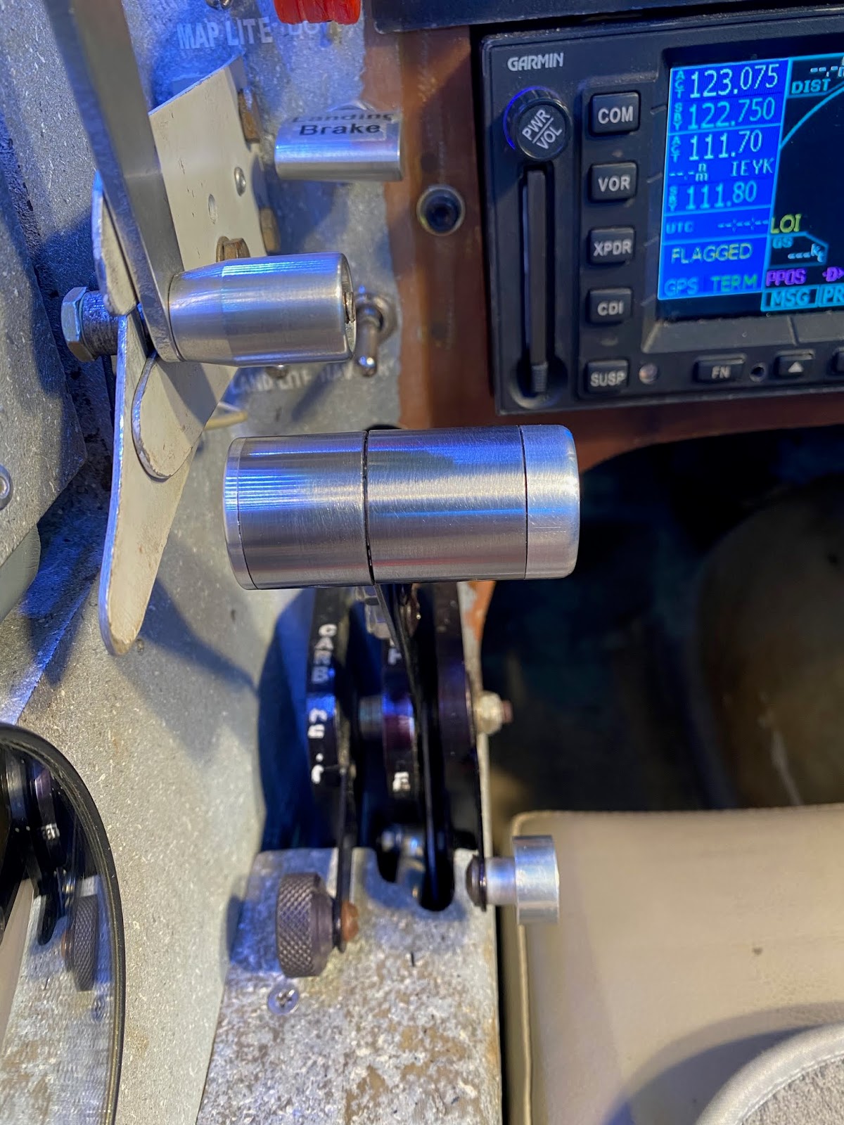
Let me first remind you what JT’s panel #4 looks like…


Not a Beasley or Wade Parton's like panel, but very effective and redundant.


And now what I envision it to be like…


Moved things around a little, and added 8 repeater lights for important GNS480 functions

Back plate got expanded a little and now has a few more holes in it

The black box sitting over the GNS480 is a Deslumpifier

The Deslumpifier is basically a bank of capacitors (plus other electronic wizardry) that keeps the GPS from shutting down and rebooting during possible engine restarts near the runway (read CHT management).


Photoshopped new panel

Wiring was a bit of a challenge, and a year after panel #4 I had mostly forgotten how to use the OmniGraffle software, so I had to figure that out all over again. Adding the two new units affected a lot of other systems due to changes in the back plate connectors choices.

This is what I have drawn up so far (bear in mind it all could be wrong and/or change at any time)


Instrument panel wiring

Radio and audio panel wiring

Infinity stick and Push To Test wiring

Instrument panel power delivery wiring

ADS-B out wiring

ELT wiring


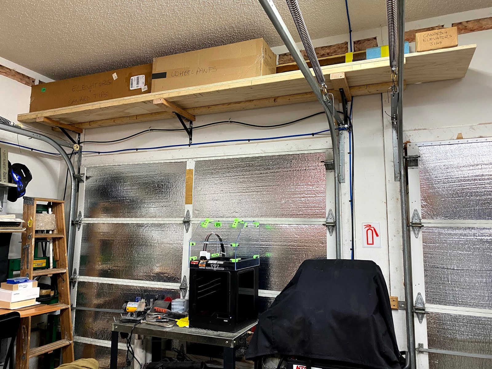
So, we are talking about doing quite a bit of work during the colder months of the year in a cold and dimly lit hangar that is 45 minutes away from my home. I am sure I could do a  much better job in my shop at home since it is insulated, heated/cooled, electrified (new 250A panel), and brightly lit by twelve 4’ fluorescent lights, plus I could work in my pajamas.

As much as I weighted the pros and cons of taking JT apart and bringing it home versus working in the hangar, it was difficult to make that decision, but eventually I elected to work from home.

Next time I’ll go over what it took to bring JT home.


Monday, December 30, 2019

Throttle lever - Part 1

JT’s improvements continue

If you fly long enough, you too will eventually experience a faulty transmit switch. 

There are many reasons why this might occur, like getting hammered all day long, but it is generally just a minor inconvenience to be fixed upon one's return home, since most us hardly ever even need to talk on the radios. 

Flying IFR though, communication is the name of the game, and anything that impairs this ability might lead to filling unpleasant paperwork at the end of the day, depending on the amount of ATC involvement needed, if you know what I mean.

Boeing obviously thinks having alternate ways of transmitting is very important, as I counted at least 10 Push To Talk (PTT) switches in the cockpit last time I flew a B767. So, I decided to add a second PTT switch on JT's throttle lever for redundancy, and to allow the left hand to pick up some of the work when the right one is busy with other tasks, like writing down clearances.

One extra feature of this additional switch will be a direct connection to the PTT circuit of the radio, bypassing all other wiring bundles, and serving as a backup way of transmitting. 

Unfortunately the current throttle lever couldn’t support a PTT button, so I had to design a new one that would.


Proposed new throttle lever

The switch will be the same kind I used in the Push To Test panel annunciator
A steel boss will be welded to the tab. The handle will mount to it.

It all started with leftover a 4130 steel tube, and a 2024 aluminum bar.


Nothing ever goes to waste in a machine shop

3D printing the end cap allowed me to visualize and play around with what I was trying to produce, and confirmed its dimensions would work.


Testing the business end in ABS

With the dimensions finalized I fired up the CNC mini-lathe and went to work on the aluminum bar.


The aluminum end cap is taking shape

End cup finished with PTT switch

Not sure of how long the lever should be, I left it extra long, to be shortened later.


Handle assembly

As in my drawings, I welded a boss to the replacement throttle lever tab which will be used to secure the actual handle.


Boss welded to the tab

Boss back side

Handle mounted to the boss

Oversized handle assembly

Old and new throttle levers


Of course the new lever was ridiculously big, and though it did feel great to work with, it had obvious drawbacks…


This size handle covers up the radio... 

... and cannot be pulled back to idle.

… so I went shorter, much shorter.


This looks more the part

Shorter was definitely the way to go, but now it was a bit too small to handle comfortably, so I decided to double it up like the original one. The problem with this idea was that to look good, the bosses on both sides would have to be perfectly lined up and concentric, not an easy feat with welding.

After mulling it over for some time, I decided to make a welding jig to hold the second boss concentric to the first one while I welded it. This second boss would be slotted to allow the PTT wires to come out of the bottom.


Using the cut off handle piece as a jig 

Sliding the new boss into the welding jig

New boss perfectly aligned to the old one, ready to be welded.

I started with a couple of tack welds in the jig…


TIG welding a couple of tacks

The two tacks will hold the boss in place for final welding

… then took it out of the jig to do the actual welding.


Second boss being welded to the tab

Welding completed, bosses lined up and concentric.

The jig did the trick, and both sides of the throttle came out  looking parallel and concentric.


Both sides of the throttle handle mounted

I'd say the welding jig was a good idea

The PTT wires will eventually come out of the bottom, and be routed through the throttle panel in a manner yet to be determined.


I staged this photo to show where the wires will exit the throttle lever

Meanwhile, before going too far with electrical connections, it was time to put it in the plane and go fly around a bit to make sure no unforeseen issues would crop up.


The new lever is no taller than the old one was

There is still room to shorten the right half further. Size however, rather than symmetry, was the only requirement.

Throttle at idle
Clearing the canopy latch bolt was the limiting factor on the outboard side.

I’m glad to report the new throttle lever has been working great over the past half a dozen flights, so I shall move on to wiring it in Part 2.


Sunday, November 17, 2019

Shop preparation - Part 7

Large parts storage

Thinking too far down the road can occasionally have negative consequences, and being emotionally ok with not doing so can prove to have some advantages. 

Getting overwhelmed by future details will definitely put a chill on one’s aspirations, and I’m pretty sure I would have never started this project had I required all the answers ahead of time. 

One needs to allow for the vagaries of life to do their thing, and not get too wrapped around possible future events.

One item I had not given a lot of thought in the past was large parts storage, and with the canard sitting unfinished on my table for the past three years, this subject became unavoidable.


Running out of space fast

In case you wondered, I did pitch the typical “May I store it in the house?” cry for help to my wife, even though I was fully aware of the impossibility of maneuvering the 11 foot long canard through the small corridors of the house.

After the millisecond it took her to decide against it, I resigned myself to building some kind of storage solution in my already overcrowded shop, and I immediately identified a pretty large area of untapped potential above the garage door.


Promising new storage prospect

Before even thinking about storing the canard though, I needed to finish the post-glassing cleanup that was so rudely interrupted when JT’s avionics wizardry got delivered in the summer of 2017.


Gotta get rid of the Bondo blobs, the red tape, the fiberglass over it, then sand the transition smooth.


A razor knife and a sharp chisel work best

Sanding the transition smooth

Now, let’s get back to the storage…

Though I needed to store large parts, weight would not be substantial. This allowed me to design a shelf with only two heavy duty metal brackets solidly attached to the garage door posts with lag screws.


1000 lbs heavy duty shelf bracket

Shelf coming together

I did recycle two 10 foot beams used in the building of the straight tower of Pisa to span the brackets, and because weight was not an issue (but maximizing available volume was), I laid them on their wider side, accepting that they might sag slightly if too much weight was to be applied.


Second crossmember attached

Before going too far with this design though, I decided to stress test the structure to higher than intended rating.


Good enough for me, good enough for the canard.

I then finished up the shelf by covering the span with pine plywood screwed to the crossmembers.


Adding a floor

But the more I looked at the shelf, the more I wished I had added a center support. So, I went back to the store and picked up some more hardware to take care of this issue.


Jacking up the center section

Third member reporting for duty!

Installing the center support

With the canard cleaned up and the shelf completed, I reused the foam the canard was cut out of, as a base for long term storage.


Taking no chances with this baby

Storing the canard leading edge down will prevent any warping

That's one out of the way storage. Love it!

Next thing you know, other items cluttering the shop ended up filling the unused portion of the new shelf.


New storage is getting popular already

Crap! It already looks like I might need to build more shelving in the future. 

Good thing I never plan that far ahead.