Chronicling my Long EZ construction (and a few other things).
Disclaimer
This blog is for entertainment purposes only, and is not meant to teach you how to build anything. The author is not responsible for any accident, injury, or loss that occurs as a result of reading this blog. Read this blog at your own risk.
This is my sixth consecutive year attending CSA’s Rough River fly-in, I am a proud repeat offender. As a canard builder it is more of a pilgrimage than just a fly-in.
In RR you feel like these people “get you”, and for a couple of days you are no longer the weirdo building a backward looking airplane in a space that should have housed a car, but a forward looking superhero able to create awesomeness from nothingness.
This year, Wade and I joined the ranks of those who flew there, and while we did not do it with our own build yet, touching down in Rough River was like a home coming.
Attendance was the highest I’ve ever seen, I think the count was around 80 planes, 69 of which canards.
Worthy of notice is the fact that Terry Lamp, the builder who’s plane I am now flying, was in attendance, and it was awesome being able to reunite the two of them after a 9 year separation.
Terry and I got to talk shop, compare notes, and go flying together. It was truly a fantastic time, highlighted by some of the best weather in weeks.
Terry's flight
I said in the past I wanted to give builders rides whenever I’d fly to Rough River, and I was able to keep my promise by taking Mike Beasley, Terry Lamp, and Wade Parton flying. Ary Glantz was unfortunately not in attendance, or it would have likely been my next “victim”.
The trip back (185 kts GS)was as incredible as the trip over (175 kts GS), we flew at 11'500 ft and 2500 rpm, and got 6.5 gph.
Terry has built an awesome airplane, and I can only hope that my airplane will prove to be as good as his.
I decided to use an OLED (Organic Light-Emitting Diode) screen for displaying Pitot probe and nose foam temperatures. OLEDs have a few advantages over regular LED displays among which is not needing to be backlit, which improves the depth of the black color, reduces power consumption, and eliminates additional sources of light in the cockpit.
The 1.5” unit I purchased (3.8 cm) came from Adafruit Industries, and was probably originally intended to be used on some older cell phone. The good news for me is that I should be able to wire it to the Arduino's digital outputs, and program its behavior via software (C++).
SSD1351 color OLED display
To answer your next likely question… “No, I have never done this before”, but then again, I also have never built a plane before, so we shouldn’t let a little challenge slow us down.
Back to the screen…
I only intended the screen to be used during the initial testing phase to verify my expectations of the Pitot tube effectiveness, and make appropriate changes to the power supply unit, but it could be left in the cockpit if one wished.
The main purpose of course would be to display the actual Pitot temperature, and also the temperature of the foam surrounding the Pitot installation. The foam being the weakest thermal link of this installation.
The display arrived with the pins not connected, so some soldering was required.
Back side of the SSD1351 as it came in the mail
With those in place, it was time to make the connection with the Arduino, and make sure I could get the screen to work.
The serial connection only takes 7 wires, and it's just fast enough for this project.
There are two different ways to hook this screen up, I had to go for the slower connection because most of my Arduino digital output pins were already spoken for. It’s still plenty fast for what I will use it for, but I also lost the ability to use the micro SD port on the back side of the screen.
With a little more work I was able to make the Arduino write some text on the display. The fist time you do this is very exciting.
Getting the screen to show something
When I went to integrate the OLED into the Pitot heating circuitry, I had barely enough digital output ports to connect it, so I ended up connecting the air/ground logic switch input to an analog port. Turns out you can use analog ports as digital, but not the other way around.
Here’s the “spaghetti diagram” of the working Pitot heating system with the OLED…
In case you were wondering how it all fit together
Because I needed a custom enclosure for the display, I decided to design one myself, then 3D print it in ABS on the Zortrax M200.
Of course I had to recreate the OLED in CAD first.
Virtual OLED drawn in Fusion360
Actual OLED
Yes, the bent pins and the soldered tips were a pain to draw.
With that done, I designed a small enclosure for the cockpit.
The base of the enclosure...
... with the OLED installed...
3D printed enclosure
... and the top cover on.
One thing that bothered me about having such a big screen, was using it to display just two numbers, so I started thinking about adding a graphing window for the probe temperature in the bottom section of the screen.
This is the part that took the most to get right, because I had to develop the code to control every pixel of the graph individually and continuously. For example, in order to represent the passage of time, I needed to shift the graph to the left, and to do that every pixel needed to be deleted individually (read "overwritten in black"), and redrawn one pixel to the left at every measuring cycle, while the new temperature reading would be added on the far right of the screen.
It all took some time to get right, but this gave me the ability to monitor the temperature trends in real time, all the while being able to look back at a couple of minutes of historical data as well.
I bet you’ll like the results.
Testing the newly developed graphing software
This almost creates a TMI (Too Much Information)situation, but it’s perfect for testing purposes, where you want to know everything that is going on with your installation.
Talking about TMI, I wanted to show Wade how the air/ground logic switch would affect the Pitot, so I shot a quick video for him that ended up being too long to sent, so I threw it on YouTube.
Testing the code for the air/ground logic
In the video I am doing the switching by hand, but on the final airplane installation an air pressure activated switch will automate this task.
The only thing left to do was to rig up my car and go collect some actual data on the road.
Official "EZ shop research/test vehicle"
Needless to say, this did attract a lot of attention on the highway
A view from the inside
After quite a few runs with marginal to disappointing results, I diagnosed a weak battery, and replaced it with a known good one. Things improved immediately, but it was too late in the day to run all the previous experiments again, tough I was able to run a static ice melting test.
"Severe icing" condition encounter
At this point, I am comfortable saying that I might be on the right path to cracking this "nut" once and for all. More testing will be necessary to confirm my expectations, but I feel like I am getting really close to a final solution.
While I have not posted recently, I have not been completely idle either. I am nearly done with the right longeron repair, and have made a lot of progress on the heated Pitot tube. More on these in the next few posts. Today I wanted to update you on my flying activity with N977JT. One of my biggest surprises came from the insurance company, when they required 10 hours of solo time before I could carry any passengers. Now, I usually log ten hours of flying time in just one day at work, so it really didn't sound like much initially, but it actually took forever to complete them, in part due to the terrible heat wave we have had in the past two months. With the hours finally checked off, my first order of business became to rectify a terrible wrong. There was still one builder out there who had worked tirelessly for the past 6 years building his Long EZ, and had never even been in one, let alone fly in it. I am talking about my buddy Wade...
Wade and me afterward
It was with immense pleasure that I was able to finally get Wade in the air on his first Long EZ flight. He will also forever be my first Long EZ passenger. Wade was able to get a few shots of our departure and put them together in a short video I will repost here...
We spent a good hour and a half having a great time, and he got to fly it from the back seat to his heart's content. He truly loved it, and the flight confirmed to him he had made the right choice of airplane. "Wade... I love you Man!"
Well, if you were following me on YouTube you would have already known, but since "the cat is out of the bag" I might as well make it official...
I have purchased a beautiful flying Long EZ, and made my first solo flight with it this past week.
Marco's new Long EZ
Before I go too far talking about it, let me just explain that nothing else has changed, I am still building my own Long EZ, perhaps with more gusto now. As a matter of fact, I have been putting quite a few hours in the shop lately, but this time I did it because I wanted to, not because I needed to. I went to look at this plane with Wade Parton for Chris, a friend of mine who was interested in purchasing it. Wade and I were the "experts" on Long EZ construction.
Wade, Chris, and me checking the plane out.
I loved the plane at first sight, and the closer I looked at it the more I liked it. Wade loved it as well, and we both told Chris to absolutely buy this plane. Talking to Chris the next day, I found out that he had decided not to purchase it. I think his wife was looking for something with more seats. Well, you can guess what happened next... rationalization is a powerful mental mechanism, and I fell for it head first. "Darn it!" ;-)
To get ready for my first flight I flew a few hours in a Diamond DA20, and a few more in a 200hp RV6A, all of them with flight instructors.
I really liked the DA20
First time in a small airplane in 20 years
This is one powerful aircraft!
I totally credit my easy solo flight in the Long EZ with the time taken to fly these two very different airplanes.
Because I am used to how a Boeing 767 lands, I needed the most help and practice in judging the last 20 feet of altitude more than anything else.
I am very thankful to my patient flight instructors for putting up with me in the 110ºF heat-index weather.
Let me take you with me now on my first solo flight in the exquisite Long EZ Terry Lamp built.
By the way, this video was not staged, I just thought of turning my iPhone camera on half way through the downwind leg, so please excuse the camera angle, perhaps you might see forward a little bit in my sunglasses.
Marco's first long EZ solo flight
The flight went great, and I had a lot of fun despite the heat. I'm not sure whether or not I should feature this plane in the blog in the future. Perhaps many of the lessons Terry learned that are embedded in this plane will find their way into mine, and then it will make sense showing them. Let me know what you think.
Technically it is no longer a voltage regulator, but I decided to keep the titleseries going to make it easier to follow my quest to intelligently power the heated Pitot tube, so please excuse the title.
As you might remember, the last time I took a stab at this I had reached unsatisfactory results after testing my own voltage regulator based power supply design.
The biggest issue was that the air blast simulating the flight environment sapped way too much heat from the tube, rendering it useless. On top of that, time to reach full heat was also substandard, taking up to 12 minutes to reach 200ºF.
In other words, while I successfully tamed the heat to the Pitot tube, I could not control it as I needed to.
Looking back to a comment from a reader at the bottom of “Voltage regulator - part 1”, I started thinking that perhaps I could program a micro-controller (basically a tiny computer) to purposefully turn on and off the full battery voltage to the Pitot tube in order to reach my desired temperature more quickly.
Not only that, but I might be able to use a thermocouple to report back the actual temperature of the probe to the computer, and cleverly adjust the power output based on that information. I could then automatically add more power ON time for decreases in temperature due to higher airspeed, rain, or icing conditions, or more power OFF time for the opposite set of circumstances, like a raise in ambient temperature, or a slower speed (slower air blast) during the approach and landing phase of the flight.
It was worth a try, so I started freshening up my C++ skill set, this time as it related to micro-controllers.
Pretty good book, however prior C++ knowledge is definitely advantageous.
Believe me when I say the title of this book was misleading, it definitely took more than 24 hours to get it all figured out, but from what I learned I was hopeful I had a better path to reach my goal.
What I would need to test this idea were an Arduino-style micro-controller, a thermocouple, a 10 amp relay to handle the full 7 amps coming from the battery all at once, and a breadboard.
Everything is held together by a custom 3D printed base
The system worked, and I could control the temperature at will from ambient temperature to the full 700ºF that the full ON battery power is capable of. Of course the software took the longest to get right, and went through many revisions, but I am happy with it now.
In a later version of this system, I added a second thermocouple to be buried into the foam of the Long EZ’s nose, right outside of the G10 Pitot tube insulator. This second sensor makes sure that if there were any high temperatures reaching the foam, the probe’s heat would get switched to a lower power mode and not burn up the airplane’s nose.
Note the 2 thermocouples
The nicest feature of this new system is its ability to react dynamically to changes in the environment without input from the pilot, and maintain any desired temperature within approximately ±15ºF, after a very short adjustment period.
Let’s take a look at some test results…
These test results are an order of magnitude better than those of the voltage regulator
The three series represent different sampling rates of the thermocouple, with the highest one generating the most precise tracking of the set temperature of 200ºF as expected.
Completely satisfied with the results of these tests, I started prepping for the first test unit, using an even smaller microprocessor.
CAD drawing of the interior of the planned test unit
Eventually, even this layout will have to be shrunk to better fit the small confines of the EZ’s nose.
Zortrax M200 delivering the goods in ABS plastic
Testing the layout in real life
All wired up and ready to go
Vented enclosure cover
For this test unit, I am also planning on adding a cockpit display of Pitot and Foam temperatures using a serial OLED 1.5" (3.8 cm) color display.
Today I'll show you how I repaired the busted longerons. If you don't know or don't remember why they have to be repaired, check out my previous post about it. I will start with the left one. The right one will be made whole in the same manner.
Here's how it all went down...
The first order of business was to develop the easiest, most reliable, and reproducible way to precisely cut the longerons with a 7:1 ratio. You see, while this cut is pretty easily accomplished over the bench, it is no longer so once you are working suspended in mid air over the fuselage, nevertheless the parts still have to match precisely for the fix to be strong.
After a few failed wooden jig models, I decided to leverage the power of the recently acquired 3D printer to design a precise 7:1 custom wedge that would accurately mate to the longeron, minimize the chances of mistakes and misalignments, and allow me to concentrate on operating the hand saw correctly, instead of keeping track of multiple variables at once.
Ok… I did have to make three of them before I got one that I was happy with, but that seems to be the perpetual theme of this build anyway.
Warning: Some pristine spruce longeron stock was harmed in the testing of these ABS jigs.
Yep, the nail holes were 3D printed right into the sides.
Pretty wild, isn’t it? Let see it in action on the fuselage!
The lower tab was mede for pushing against the sidewall (as depicted).
Using a drill to transfer the nail holes to the longeron
The small ABS "bridges" ensure perfect placement of the jig on either sides of the longeron
The "bridges" get cut away in the process
Almost there
ABS is pretty tough, and resisted the saw well with only minimal damage.
I decided to remove the busted foam and fill the space with flox.
Outer skin left intact to form the new old-shape
Tongue depressor wrapped in duct tape forms the back end wall
Adding flox
Another tongue depressor forming the new inner sidewall (less sanding that way)
A day later, with all the masking removed.
Same thing after a little sanding
Outside view of the floxed part. The marked delaminated triangular piece will be replaced soon.
Using the same ABS jig on the table this time, I cut the longeron stock that would replace the broken one.
Last action this jig will ever see
On the inside of the fuselage I added two UNI plies that replaced the missing inner skin. This part of the repair was a bit of an academic exercise, since a big hole will be cut right over the top of the repaired section to fit the Center-Section spar.
Redis the UNI patch I just added,purple is the hole I will have to cut for the Center-Section spar.
With the new inner skin in place, I test fitted the replacement longeron on the fuselage, and with the tiniest amount of sanding I was ready to mix some flox.
Test fitting the longeron splice
Flox added to the joint
Longeron splice curing overnight
Same thing viewed from below
The next morning every distant doubt about lack of strength vanished after I tried picking up the fuselage by the new longeron splice uneventfully.
"Yep, that will do!"
Now, according to my engineer guide, the most important part of this repair was to take place. The replacement of the UNI outer skin (layer by layer, oriented accordingly to the original specifications) had to be carried out correctly. A lot of this replacement fiberglass would eventually be swallowed by a gaping hole for the Center-Section spar, but some would not, and it would have to tie in to the lower layers as specified on page 3-22 of the plans, section 4.2 (Large Defects).
How to fix large defects
A visual representation of how the fix is to be accomplished
The first area of concern was a slight delamination of the outer skin. This would have to be cut off and the surrounding area included in the overall skin replacement scheme.
The top right corner has to go
Foam and flox is revealed underneath
UNI plies exposed. Note the different orientations of the plies.
Corner absorbed into the overall repair scheme. The purple area will be removed for the CS spar
First off though was replacing some missing foam with micro.
Damming the corner
Building up the foam with micro
Whole area prepped and ready
Then came two UNI plies in the original orientations down to the 3” line, followed by a bigger BID piece extending 1” further (4” line on the fuselage). Plenty of peel-ply went over it all.
First UNI layer cut to size to the 3" line
Peel-ply going over the 2 UNI and 1 BID plies
A view from inside the fuselage
A day later the peel-ply came off, and the repair to the outer fuselage skin was completed.
Peel-ply removed. Note the large area to be removed for the CS spar.
Close up of the repair
Repair seen from the front looking back
The inside of the longeron still laid bare, but would receive one ply of BID, plus one more over it all, next.
Inner part of the longeron will get 2 plies of BID
Area sanded and prepped
Pure epoxy mixed with a little Cab-O-Sil to prevent runs
Cab-O-Sil is a fumed lightweight silica thickener used to reduce the flow of epoxies on vertical surfaces.
Flox applied from a plastic bag
Flox fillet under the longeron
2 ply BID pre-preg
Pre-preg folded to follow the contour of longeron and sidewall
Pre-preg plastic backing removed
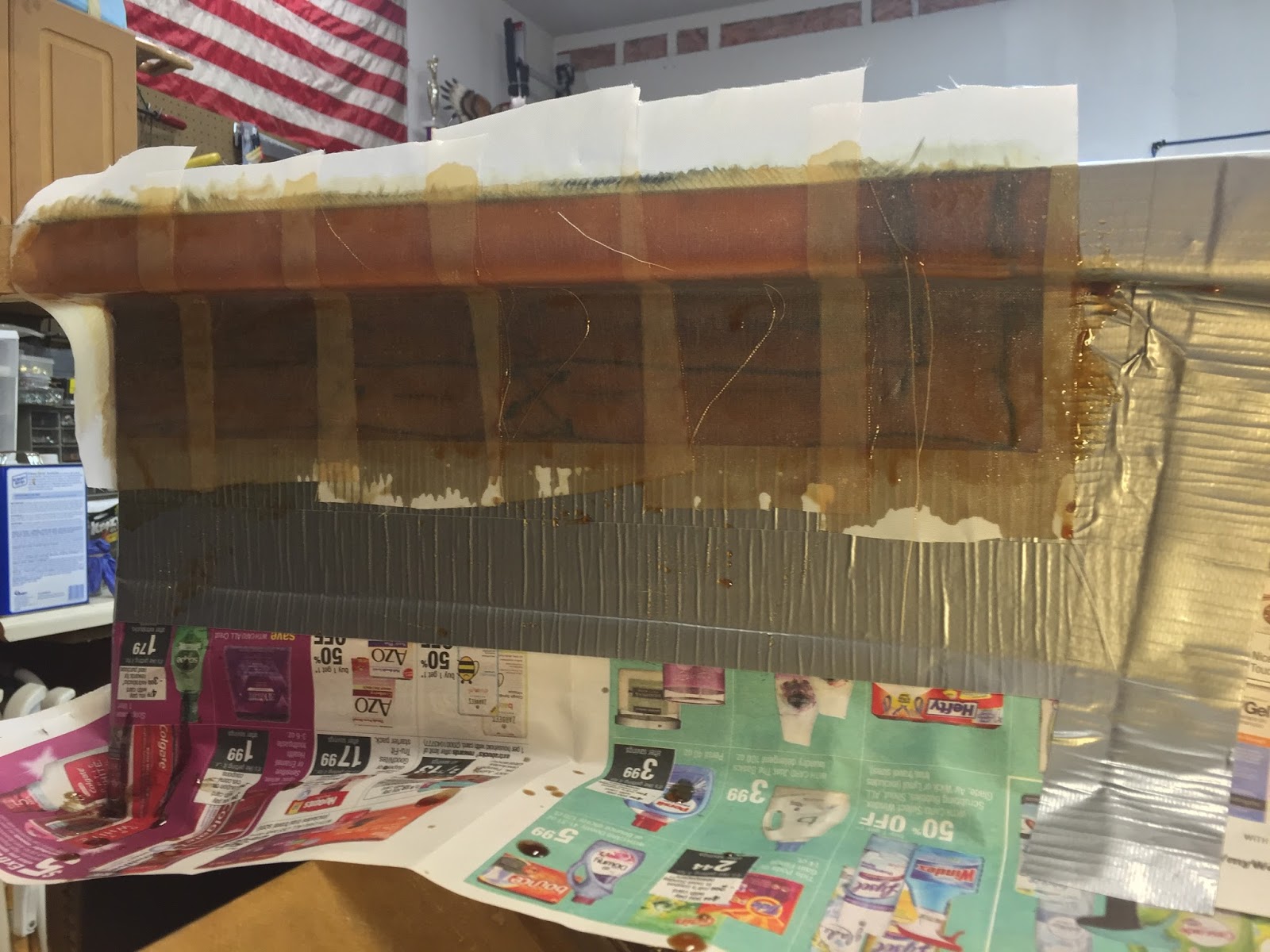
Peel-ply over the repair for the overnight curing cycle
After it cured, I removed peel-ply, duct tape, and newspaper. Then I sanded the rough edges smooth, and this is what I was left with...