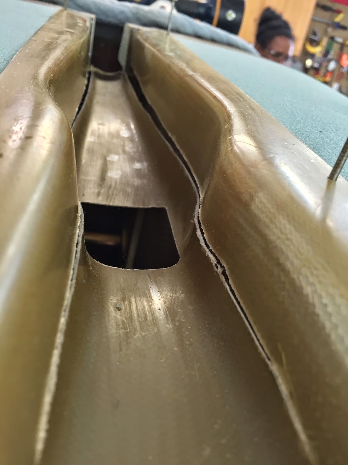
First in flight! (2.0 hrs)
Note: At the beginning of this journey I promised myself I would share both the good and the bad, so that we might all learn something from my successes, and mistakes. It is in this spirit, though with some unease, that this post gets filed.
Today I was planning on talking about nose contouring, but I will talk instead about a fuselage that was just too eager to get airborne for its own good. And getting airborne it did, beating all of my other builder friends by becoming the first in flight!
Nearing the end of my CNC upgrades, I decided the EZ had patiently waited long enough for my shenanigans to end, and it was way past the time to get back to the main focus of this blog. So, I started my day with two solid hours of sanding on tough blue foam, employing just about every tool in my arsenal.
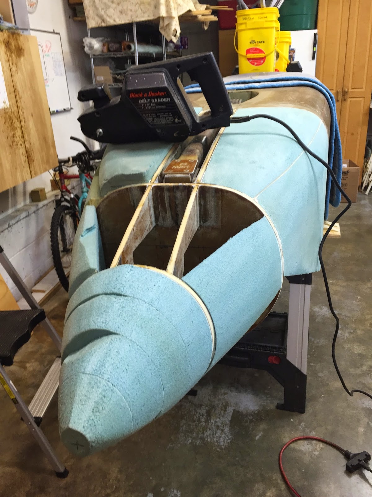 |
| Picking up where I left off |
 |
| With this much foam to take off, anything powered is of great help. |
 |
| Bottom of nose mostly contoured |
I was feeling completely “in the zone” once again, happily sanding every which way, yet utterly unaware of the doom that would be shortly upon me.
Up until this point, the fuselage had rested upside down on two slightly modified saw horses.
 |
| Saw horses with much wider wooden tops |
Ever since the main gear was removed, the nose became much heavier than the tail, so a considerable amount of weights was added to the back helping to hold the tail down.
 |
| Safety precautions prior to sanding |
Then suddenly, and without a warning, IT happened!
The nose of the plane took off from under my hands shooting up to the heavens like a Space Shuttle launch, amid a deafening and frightening metal roar. It was all I could do to get out of the way, and duck for cover, as my brain struggled to process the cause of my sensory overload.
Time slowed to a crawl, and my mind began parsing the metallic thunder into hundreds of individual pings, like steel bars hitting concrete…
Oh no… this can’t be happening!
In the few seconds it took Gina to appear at the garage door, sure to find little left of her husband, the praying for a miracle, and the cursing for my stupidity had already begun, while the fuselage rested ungraciously on the floor at an odd angle, reminiscent of a fractured and dislocated limb.
Things were looking tragic, and the only question in my mind, as I raced to the scene of the accident, was no longer IF there had been damage, but HOW extensive it was, and whether the project was still viable, or no longer so.
Happy to see me standing, Gina helped me pick up the seriously wounded bird, then sit it back on the same saw horses from which it had worked itself loose, and clear up about 100 lbs of steel and aluminum from the garage floor.
I, on the other hand, still shell shocked by the violence my negligence had inflicted on this delicate creation, was preparing emotionally for the worst. I was sure the damage was unrecoverable, and perhaps unconsciously began mourning the loss of years of work, and blaming myself for allowing it to happen.
Upon initial inspection the list was short but illustrious, featuring outer skins, inner skins, foam cores, and last, and certainly not least, two broken longerons.
HOLY SHIT!!! (please pardon my volatile emotional state)
 |
| Right longeron damage (fuselage upside down as it fell) |
 |
| Right longeron and outer skin damage (fuselage upside down) |
 |
| Left longeron damage (fuselage upside down) |
 |
| Left longeron damage (fuselage upside down) |
 |
| Left longeron and outer skin damage (fuselage upside down) |
 |
| Left longeron damage (fuselage right side up from now on) |
 |
| Left longeron damage |
 |
| Right skin and foam damage |
|
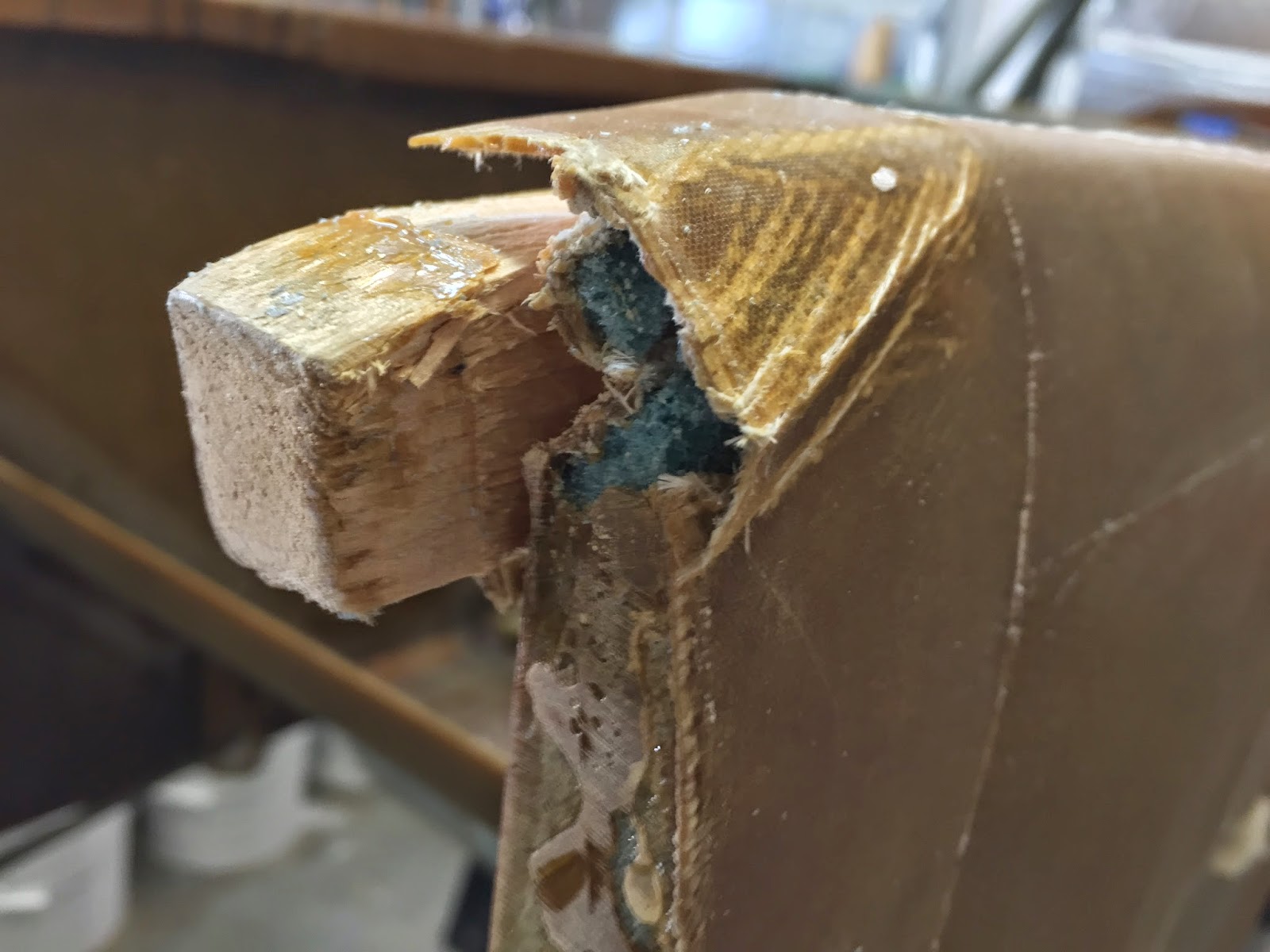 |
| Right skin and foam damage |
|
 |
| The whole picture (left view) |
|
 |
| The whole picture (right view) |
|
I left the shop near tears, hoping that physical distance allowed me to wake up from the nightmare.
What followed next was a “merry go round” of feeling sorry for myself, mixed in with flashbacks, where I relived the moment of the accident, like a car crash you see happen, but are unable to stop, and crazy ideas of setting whatever was left of the project ablaze.
At this point, I was sure the damage to the structure had to be too great to recover from, and since I wouldn’t accept anything less than 100% strength in a possible repair, I saw no way for this project to continue.
But that's when being part a community of builders with a lot of experience to draw upon, becomes invaluable. In situations like this, when your disappointment blinds you to many obvious solutions right within your capabilities, it allows you to realize that maybe things are not as desperate as they initially had seemed.
You can download the circular online for free (turns out I had already bought a copy for the shop), and the relief I felt reading chapter #1 was priceless. In it are techniques that allow you to repair broken wing spars made out of wood!
 |
| It had been on my desk forgotten and unopened for months under a pile of other papers |
Think about it for a second… the wing spar is the most critical structure in an airplane, and the FAA allows you to fix it (within certain parameters) on a certified aircraft. All I broke were two small longerons, definitely important, but certainly not as critical as a wing spar.
I felt I had been granted a much needed second chance, and that I should become really intimate with this chapter, which by the way is greatly interesting, and should be required reading (at least in part) by anyone using wood parts.
Next, I will parse and paraphrase some of the important facts I learned from AC43-13b, and that apply to my situation, so that you might be able to follow the repair process to come with a better understanding of what I am doing, and more importantly why, as the methodology might appear slightly different from what we are accustomed to.
Some things will appear obvious, other might not. Here we go…
MATERIALS AND PRACTICES
Quality of wood
All wood and plywood used in the repair of aircraft structures should be of aircraft quality…
Substitution of original wood
The wood species used to repair a part should be the same as that of the original part whenever possible, however some permissible substitutes are given in table…
Effects of shrinkage
Thoroughly seal all wood surfaces, particularly end grain and bolt holes, with varnish, epoxy, or other acceptable sealer to slow or prevent moisture changes in the member…
Adhesives
Adhesives acceptable to the FAA can be identified in the following ways: Refer to the maintenance or repair manual for specific instructions on acceptable adhesive selection for use on that type aircraft… Synthetic-resin adhesives comprise epoxy… Epoxy adhesives are a two-part synthetic resin product, and are acceptable… They have been found to be much less critical of joint quality and clamping pressure. They penetrate well into wood…
Bonding precautions
Satisfactory bond joints in aircraft will develop the full strength of wood under all conditions of stress. To produce this result, the bonding operation must be carefully controlled to obtain a continuos thin and uniform film of solid adhesive in the joint with adequate adhesion and penetration to both surfaces of the wood…
Preparation of wood surfaces for bonding
It is recommended that no more time than necessary be permitted to elapse between final surfacing and bonding. Keep prepared surfaces covered with a clean plastic sheet or other material to maintain cleanliness prior to the bonding operation. The mating surfaces should be machined smooth and true… Planer marks, chipped or loosened grain, and other surfaces irregularities are not permitted. Sandpaper must never be used to smooth softwood surfaces that are to be bonded. It is advisable to clean both joint surfaces with a vacuum cleaner just prior to adhesive application… Roughening smooth, well-planed surfaces of normal wood before bonding is not recommended. Such treatment of well-planed wood surfaces may result in local irregularities and objectionable rounding of edges. When surfaces cannot be freshly machined before bonding, such as plywood or inaccessible members, very slight sanding of the surface with a fine grit such as 220, greatly improves penetration by the adhesive of aged or polished surfaces. Sanding should never be continued to the extent that it alters the flatness of the surface. Very light sanding may also improve the wetting of the adhesive to very hard or resinous material…
Applying the adhesive
To make a satisfactory bonded joint, spread the adhesive in a thin, even layer on both surfaces to be joined. It is recommended that a clean brush be used and care taken to see that all surfaces are covered. Spreading of adhesive on only one of the two surfaces is not recommended…
Clamping pressure
Use the recommended pressure to squeeze adhesive out into a thin, continuous film between the wood layers. This forces air from the joint and brings the wood surfaces into intimate contact. Pressure should be applied to the joint before the adhesive becomes too thick to flow and is accomplished by means of clamps, presses, or other mechanical devices. Nonuniform clamping pressure commonly results in weak and strong areas in the same joint… Insufficient pressure or poorly machined wood surfaces usually result in thick bond lines, which indicate a weak joint, and should be carefully guarded against. Some epoxy adhesives require much less clamping pressure to produce acceptable joint strength.
REPAIRS
General
The basic standard for any aircraft repair is that the repaired structure must be as strong as the original structure and be equivalent to the original in rigidity and aerodynamic shape. Repairs should be made in accordance with manufacturer specifications whenever such data is available.
Scarf joint
The scarf joint is the most satisfactory method of making an end joint between two solid wood members. Cut both parts accurately. The strength of the joints depends upon good joint design and a thin, uniform bond line. Make the scarf cut in the general direction of the grain slope as shown in figure 1-4.
 |
| Figure 1-4 Consideration of grain direction when making scarf joints |
|
No grain deviation steeper than 1 in 15 should be present in an outer eighth of the depth of the spar. In adjacent eighths, deviations involving steeper slopes, such as a wave in a few growth layers, are unlikely to be harmful. Local grain slope deviations in excess of those specified may be permitted in spar flanges only in the inner one-fourth of the flange depth.
Splicing of spars
Unless otherwise specified by the manufacturer, a spar may be spliced at any point except under the wing attachment fittings, landing gear fittings, engine mount fittings, or lift and interplane strut fittings. These fittings may not overlap any part of the splice… Reinforcement plates must be used as indicated on all scarf repairs to spars and the slopes of scarves shown are minimum slopes.
 |
| Figure 1-5 Method of splicing solid or laminated rectangular spars |
Reinforcement plates to be spruce or plywood and should be bonded only, with the ends feathered off at 5:1 slope as depicted in Figure 1-2.
 |
| Figure 1-2 Tapering of faceplate |
This is a lot of material to digest, so I decided to first “do no evil”, or more precisely “no further evil”, by rushing into a repair job.
I will probably fix the back end after I finish glassing the bottom of the nose, this way I'll be forced to keep looking at the damage every day as a reminder to be even more careful going forward.
UPDATE
Click here to see how I will end up fixing this mess.