Disclaimer

This blog is for entertainment purposes only, and is not meant to teach you how to build anything. The author is not responsible for any accident, injury, or loss that occurs as a result of reading this blog. Read this blog at your own risk.

Saturday, March 08, 2014

Lathe improvements - Tailstock DRO

Digital Read Out

The mini-lathe has been quite an asset for the past two years, and I have learned so much using it. As good as it has turned out to be, there are a few things that have been bugging me, one of them is the difficulty to drill to a precise depth.

The only way to do so on the stock machine is by referencing some hard to see graduations on the tailstock’s quill, an approximation at best. 

Since 99% of the times the holes I drill are through holes, this issue has not been a big problem, but two years into its use, I thought there might be some improvements I could make to rectify this minor infraction once and for all, and make my turning experience a tad more enjoyable.

In the past, whenever a hole of a precise depth was called for, I have used a 2” (5.1 cm) dial indicator attached to a magnet, positioned on the tailstock, and indicating off of an aluminum plate I machined, and attached to the quill. 


Dial gauge on a magnet indicating off of an aluminum plate attached to the quill


This setup is straight forward, but presents a number of inconveniences. For one thing you subtract the reading to obtain a measurement, since the dial indicator’s shaft extends with the quill reading backward. Another issue is placement, this setup is almost as big as the tailstock itself, and gets too close to the tailstock crank not to get bumped occasionally, throwing off the measurement sought for.

A few months ago, I bought a 4” (10.2 cm) digital caliper on sale for $9.99 at Harbor Freight, with a vague idea of using it on the lathe. 


Harbor Freight #47256


Well, the time has come to put this caliper to good use.

I started out by cutting off the “inside jaws” with my bandsaw, and removing the “depth probe”. 


Removing the inside jaws


Laying the mutilated calipers on the tailstock, I decided where to attach them in order to minimize interferences with other parts, and maximize travel. 


Figuring out where to place the caliper


I eventually ended up cutting a few inches off the bottom end of the caliper as well, so that it wouldn’t hit the crank when fully retracted.

With the location chosen, I drilled and tapped the tailstock, and the aluminum plate I had previously made, on my drill press.


Drill press comes in handy from time to time

Tapping for a small screw


A couple of fastener later, and I could already test the concept.


Initial testing of the assembly


One last internal modification remained to be made, and for that the tailstock had to be disassembled.


Exploded view of the tailstock

Releasing a chuck, or a dead-center (#143) from the tailstock requires the back of the chuck to push off of the left end of a threaded rod (#139). As the quill retracts (#142) the back of the chuck comes into contact with the rod and is expelled.

Unfortunately, since I attached a thick aluminum piece to the end of the quill, it is now unable to retract fully into the tailstock, and disengage the chuck.

My first thought was to manufacture a new longer rod, but it turned out that its thread was a lefty (clockwise to unscrew), in itself not a limitation, but it also presented a metric pitch. Since I do not have gears to allow my lathe to cut metric threads, and my dies are all right handed, this proved to be a no go.

In order to lengthen the rod, I decided to drill it, tap it (imperial), and insert a bolt in it. This is a pretty normal procedure on a lathe, but with my tailstock being the subject of the surgery, it could not be counted upon. I decided to use a T socket wrench to push on the quill by hand, until the hole was deep enough to tap it.


Pushing the quill by hand (note the missing crank wheel)

¼-20 socket head cap screw extending the range of the threaded rod

A view down the quill reveals the added ¼-20 screw

The tailstock DRO modification turned out wonderfully, and it was easy to do. I can now drill holes to any depth I choose with very high precision, The DRO it is out of my way for all normal operations, and I no longer have to fumble trying to set it up and work around its mass.


Completed tailstock DRO modification


Tailstock DRO in action


Friday, March 07, 2014

Epoxy 104

Thermal runaway

I suppose it’s a bit late in the project to be talking about such things, but while this is not the first time it has happened to me, it is the first time I had the presence of mind to ask myself “Where is the nearest camera?”, before asking “Where’s the nearest fire extinguisher?”.

“What’s a thermal runaway?” you might ask, and I’m glad you did.

I hope my Chemical Engineer daughter will forgive me for butchering and oversimplifying this explanation, but here it goes...

Mixing pure epoxy from resin and hardener is an exothermic reaction, meaning it produces heat as the molecules bond to each other. 

One interesting fact about this reaction is that the warmer the components become, the faster the reaction proceeds, and the more heat is produced. 

Like in a nuclear power-plant accident, if the reaction is not stabilized by proper cooling (enough to prevent a runaway, but not too much to prevent the reaction from happening), a situation where an uncontrolled and destructive positive feedback loop takes over.

If the heat from the reaction is unable to escape, the medium warms up, and that makes the reaction happens faster, which produces more heat, which in turn is unable to escape, and heats up the mixture even more, which speeds up the reaction, and... you get the picture, things can go wrong very quickly indeed.


Exotherm positive feedback loop


The key to this process is to keep the batches of epoxy small, in order to reduce the amount of heating, and use containers that maximize external surface such as wide containers, where the epoxy can lay out thinner, and have more avenue to transfer excessive heat to the surrounding air.

Different epoxies have slightly different behaviors in regards to thermal runaway, and although all of them have the potential, I have only had a couple of issues with the West System. 

This is another situation where “supersize” is bad. In this case, I must have gotten a little greedy with my batch size, and set off the subject of the video below.


Exotherm runaway scramble!


This doesn’t mean the West System is bad, as a matter of facts it is a very useful epoxy for a number of things, and I still plan on using it for a long time to come, it just means you have to be careful, and use it as it was intended.


Tuesday, March 04, 2014

Ch. 8 - Rollover structure - part 5

Burying the nut-plates and restoring the fuselage outline (17.7 hrs)

This time around I got to take care of old business, and while there was no real rush to accomplish this, I had grown tired of the unfinished look of the rollbar attachment to the fuselage. 

As you might recall, I had carved depressions in the fuselage in order to bury nutplates below the skin, and these needed to get filled with foam, then glassed.


Right depression

Left depression


Here’s an updated cross section of the main plan...


Items to be installed in red


To make sure the nutplates won’t move in the future, I floxed the tabs holding them to the sidewalls, allowing the flox to mushroom through the lightening holes.


Adding flox to the right nut-plate bar

Nut-plate bar held in place by the roll-bar bolts

Repeating the process for the left side


Flox curing


After a few hours of curing, and before the flox hardened completely, I flattened the mushroom heads some more with my fingers, in order to increase the flox grasp on the metal. Then I left it to complete the cure overnight.


Gummy flox flattened by hand


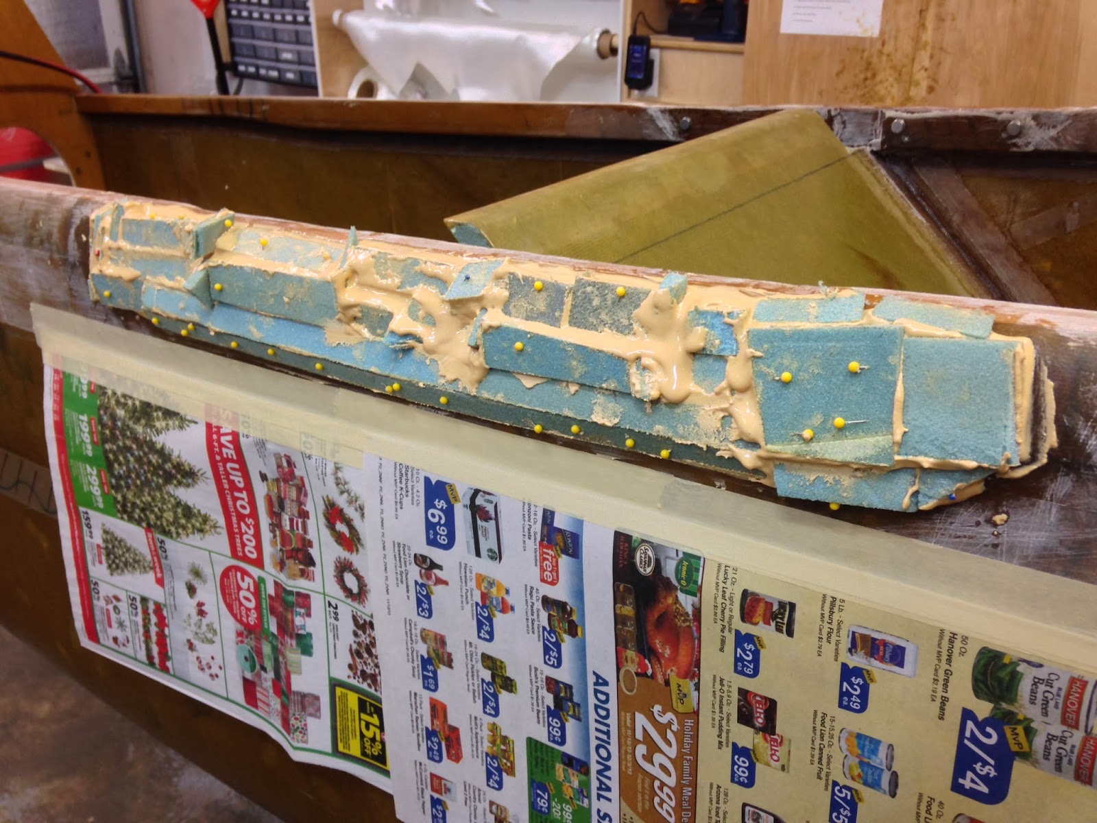
The next morning, I gathered old scraps of foam left over from cutting the fuselage sides.


Nothing goes to waste with this construction method


After mixing up some micro, I glued the foam scraps into both depressions until I filled them up, and then some.


First scrap glued into the sidewall depression

Straight pins unwittingly donated by my wife

The pins could not be saved afterward

Fighting gravity. The whole thing was slowly sliding downward.

Belt and suspenders concept


Once again, I left things to cure overnight.

After getting back to the fuselage, I spent most of the day sanding the soft foam, mixed in with fairly hard micro, until I matched the profile of the rest of the fuselage.


It felt like I was sanding all day

First contouring done

Notice the rough shape of the foam and micro

The many holes still needed to be fixed before moving on to glassing


All of that rough sanding really took its toll on foam and micro in the form of deep gouges, and holes. In order to fill them up I mixed up a new batch of West-System micro, and reapplied it.


Patching the holes

"What can I say? There were a lot of holes!"


One of the advantages of the West-System, is its fast cure time, meaning I could start sanding the same day. So, once the micro cured, I started smoothing things down all over again, until I was satisfied with the final contour.


Final contouring done

Smooth enough for glassing


At last, I was able to take a brake from sanding. 

I marked and cut all the necessary layers of UNI. First, 2 layers cut with a 30˚ bias, and laid over the depression crossing each other, then 3 layers from 52 to 48 inches long, staggered 1”, with a 0˚ bias over most of the longeron.


UNI marked for cutting

UNI before adding epoxy

2 UNI plies cut at 30˚ crossing each other, restoring the original structural integrity.

Left depression filled, and glassed.

3 UNI plies cut at 0˚ extending 52" over the longeron

Right longeron getting reinforced


Since the strakes will eventually attach there, I decided to peel-ply everything, then I reinstalled the very tight fitting roll-bar, but only after the epoxy got tacky. I did it this way in order to prevent the epoxy from being mechanically squeezed out of the fiberglass, while still allowing the fiberglass to conform to the bottom surface of the roll-bar.


Adding peel-ply

Peel-ply and roll-bar added

Left side peel-plied

Roll-bar protected with packing tape, and installed in position after the epoxy became tacky.


Overnight cure, peel-ply removal, and sanding the rough edges came next.


Removing peel-ply is very enjoyable...

...sanding isn't.

Lots of peel-ply strands, and some unevenness, required much sanding on both sides. 

The final shape came out very nice

Sand, sand, sand.

High spots were lowered a bit

Very nice profile


Recessing the roll-bar into the longeron worked out quite well, the right side ended up 0.037” (0.94mm) below the top of the longeron, and the left side just 0.016” (0.41mm). Not too bad for carpentry work.


Slight gap between the top of the longeron, and the top of the roll-bar.

0.037" gap (0.94mm)

Even smaller gap on the left side

0.016" gap (0.41mm)


Roll bar walk-around