Disclaimer

This blog is for entertainment purposes only, and is not meant to teach you how to build anything. The author is not responsible for any accident, injury, or loss that occurs as a result of reading this blog. Read this blog at your own risk.

Monday, February 11, 2013

Voltage regulator - part 2

I spent a couple hours testing the voltage regulator at 4 different input voltages (9v, 18v, 27v, and 36v). Using a spreadsheet, I recorded the output voltages generated using increasing values of resistance, as set by the potentiometer.

The most interesting thing to come out of this exercise was finding out how stable and precise this device is. As you’ll see in the video, the voltage is precisely controlled by the circuit regardless of the input voltage. 


Testing the stability of the prototype circuit board


On the heels of this successful test, I built a circuit board from a Radio Shack blank on which I soldered all the components, and a few connecting wires. This is a temporary arrangement designed to allow me to test the circuit with the actual load it will see in operation. 

The final version of this board will be chemically etched, and no extraneous connecting wires should be necessary. A proper enclosure will need to be found, including switches, lights, and other knick-knacks.


Testing the "pre-production" circuit board with a load


One additional idea that I am considering, is somehow tying the voltage regulator to the airspeed. 

This could be done via EFIS signal, or a simple airspeed switch, so that turning on the pitot heat on the ground would only bring about 150℉ (65℃) perhaps, using the 3.5v circuit, and once a certain airspeed is reached (flight mode), the 4.5v circuit could be automatically selected, generating 220℉ (104℃). 

Back on the ground after a flight, if the pilot accidentally forgot to turn the pitot heat off, the system would automatically return to low heat mode preventing any damage to the nose of the plane, or to anyone who might accidentally come in contact with the pitot tube.


Saturday, February 09, 2013

Voltage regulator - part 1


I just wanted to share the latest developments on the voltage control front.

First, I calculated the effects that different voltages applied to the heating element would have, then I proceeded to test the concept. 

The original 12 volts provided by the battery generated 80 watts at the element, and 6.6 amperes, this heated the pitot to over 700℉

By my calculations, 6 volts across the heating element would create 20 watts to be dissipated as heat, and a current of 3.3 amperes. To achieve this voltage I decided to use an additional identical heating element as a resistor, then check the temperatures.


Pitot heat still a bit high


20 watts still turned into 300℉ at the probe, this was much better already, but an even lower voltage was required.

Digging through my parts bin I found a bigger resistance, capable of dropping the voltage even further to around 2.3 volts, good for about 2.7 watts at the tube.


Voltage reduced even further


Pitot heat much cooler now


This dropped the temperature even further to an almost cool 110℉. I am obviously zeroing in to the proper voltage value, and proved that the concept is sound. There is only problem with the resistance approach, it is very wasteful of the little electricity produced on board the airplane. Furthermore, the resistance used to control the voltage also heats up, and I’d be trading heat at the Pitot tube, for heat into the cockpit needing to be dissipated at the resistor.


While the Pitot heat in the nose is at 110℉, the resistor in the cockpit is at 277℉.


The proper approach to voltage control in my case, is to build a step down voltage regulator.

Voltage regulators are “a dime a dozen”, but voltage regulators capable of handling a high current, are not all that common. The one I designed is built around a monolithic integrated circuit rated up to 3 amps, more than enough for what I am trying to do.

Unfortunately the components I needed are not popular enough to be carried at the local Radio Shack (guess how I know), so I ordered them online at mouser.com, and a week later I was able to finally test my new approach.


This looks like fun!


Success at last!


Testing with two 9 volts batteries in series


Testing with my car's 12 volts battery


The next step will be to produce a prototype circuit board, and test it against the heating element that will actually warm up the Pitot tube.


Wednesday, January 30, 2013

Heated Pitot tube

I am planning on certifying my airplane for IFR (Instrument Flight Rules) flight, so I decided to equip it with a heated Pitot. 

For those unfamiliar, let’s just say that the Pitot tube will sit on the nose of the plane and capture the incoming air pressure. Since this dynamic pressure relates directly to the speed of the plane, a flexible hose will connect the Pitot tube to the anemometer (air speed indicator), which in turn will display how fast the airplane is flying through the air. The airspeed indicator will also connect to the static ports, but that's a topic for another time (more on it here). 

Although flying into icing condition is to be avoided at all costs  due to its many cumulative negative effects, flying in the clouds is the first ingredient for an unintentional encounter with ice. 

Ice forming on the Pitot probe, and obstructing the hole through which the air pressure is sensed, would render the anemometer useless. One very effective way to combat this undesirable situation is to heat the probe from the inside, so I set out to build myself a heated Pitot tube, borrowing generously from other designs I found online.

Brainstorming with my friends Mike and Wade was very helpful, and allowed me to explore many ideas I wouldn’t have thought of by myself. They in turn got excited about what I was trying to do, and expressed interest in having one as well, and in the end I decided to make not one, but three.

Pitot number 1 will go to Mike, since he’s at the stage in his build where he can install it. The pictures and dimensions in this post are those of the tube I designed for him.


Fully assembled (heating element omitted)

Exploded view of the Pitot main components (heating element omitted)


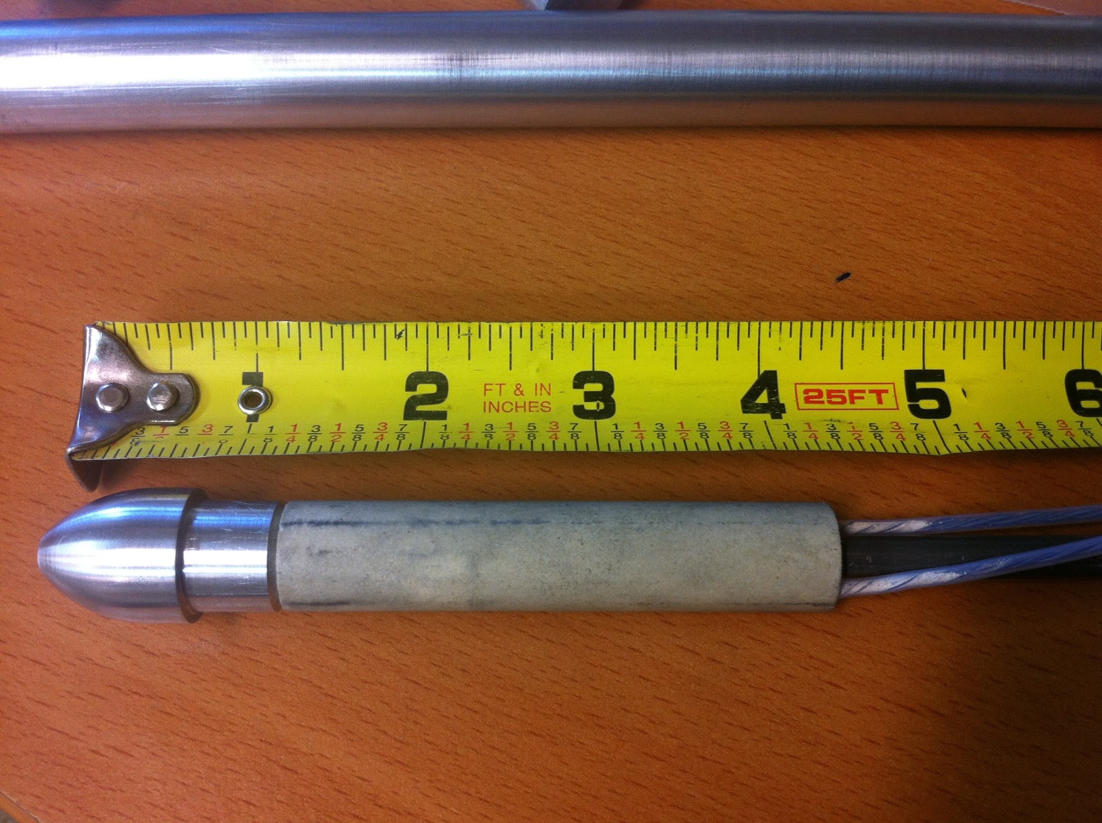
Pitot "business end" dimensions


Pitot back cap dimensions


I ordered the aluminum tubes and rod...


Raw material


... and the G10 phenolic heat insulating material, and went to work. For the record, I was trying to upgrade to G11, which is rated to 500℃, but I would have had to order $500 worth. So, G10 it was!


G10 insulator

I started working on the front piece first, using a tool called Ball and Radius Turning Tool.


Shaping the nose cone


Overall it turned out pretty much like I had envisioned it in CAD.


Nose cone 3D presentation


Installed on the outer tube


Next, I set to work on the back piece, and decided to mill 6 flats on it. This feature will allow me to tighten the finished Pitot using a 15 mm wrench, as well as tighten the quick release fitting using an additional wrench.


Tail piece 3D presentation


Mill setup for creating the bolt-like pattern on the end piece


First 2 faces milled


All 6 faces milled, and through hole drilled


Testing for size


The small hole was enlarged and tapped (NPT 1/8 - 27), and a quick release vacuum fitting installed.


Back piece ready for mounting


Installed on the outer tube


This is my first time working on a 0.75” (1.9 cm) aluminum tube of such length, as well as with the 1.25" (3.2 cm) thick G10 insulator, and I needed to update my lathe to a bigger chuck.

So, I replaced my 3" chuck with this 5" monster! 


This is a BIG upgrade to my little lathe


Chuck completely disassembled and cleaned up


Spindle hole in plain sight (old chuck removed)


New chuck in place


The new chuck, with its bigger through hole, allowed me to shove a whole foot of tubing through the spindle hole, and out the other side of the machine, enabling me to work on one end of the tube with much greater setup rigidity. 

First thing I used it for was boring the outer tube by about 10/1000" (0.025 mm), to a depth of 3.5" (8.9 cm). This created a cylindrical receptacle to house and retain the heating element in the very front of the tube, while allowing it to slide in and out easily.


Boring bar enlarging the hole


Later I chucked the inner tube, brought it down to the proper length, and cut threads on both ends (1/4-28).


Forming the threads on the inner tube


1/4 - 28 thread


Testing the threads with the nose piece


Although the G10 is there to protect the nose cone from excessive heat, keeping the heating element outside of the nose altogether seems like a better idea.

The amount of Pitot tube that will remain outside of the airplane nose structure, being cooled down by the airflow, is predetermined by the size of the Pitot nose piece, plus the heating element.


Amount of Pitot tube to keep out of the airplane's nose


The last major operation to perform on the outer tube was milling a slot for the wires.


How to align the spindle axis with the tube axis


1/4" mill ready to cut the slot


Wire slot milled


So, here is a sketch of the master plan...


Basic layout


... and the finished Pitot tube.


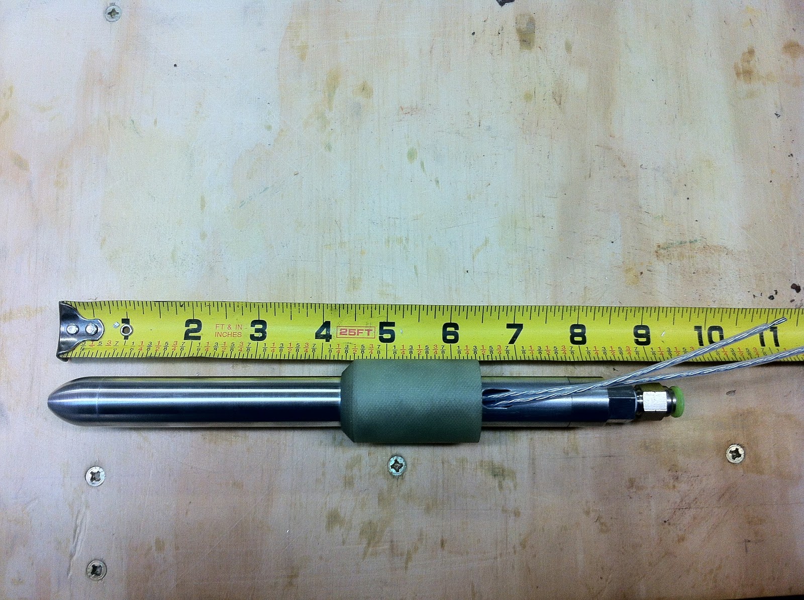
Finished Pitot


A view from the front of the airplane


As seen from inside the nose cone


6.14 oz (174 gr) including G10 insulator, 4.44 oz (125 gr) without.


Here are all the components of the heated probe together.


Disassembling the Pitot


Heated Pitot tube components


The only thing left to do was an operational check, to make sure it worked. 


Testing the heated Pitot tube


As you can see in the video lack of heat is certainly not an issue. On the contrary, the voltage might need to be stepped down some, in order to be able to control the temperature, which was increasing rapidly. 

I'm thinking a 3 way switch with OFF, LOW, and HIGH settings perhaps, but more testing is in order. At the very least, I have to find out how hot the probe really gets, and I will definitely need a better thermometer for that.


Testing the heating element


Using the wind chill formula published in this website, it would appear that I cannot rely on airflow for cooling the probe. Using 200 mph and an outside temperature of 32℉, the Pitot tube would "experience" an air mass of 4℉, for a 28℉ drop in temperature. This figure does not include the additional cooling due to evaporation/sublimation of moisture, but even if this added up to a 50℉ drop, I would still be an order of magnitude away from a manageable probe temperature.

Further increasing the speed is not an option, and and even if I could, it would rapidly become counterproductive since at speeds above 250 kts friction raises the surface temperature by roughly 1℃ every additional 10 kts. I take advantage of this effect often at work, to manage the fuel temperatures of Jet A when it gets close to reaching the freezing point (-41℃). 

The element is obviously putting out excessive heat. I need to find a final solution to this problem, and it is going to be an electrical one. 


Meanwhile, Mike has received his tube, and he seems really pleased of how it has turned out.


If that is not a happy face, I don't know what is!


The big picture


Nose detail


I will be working on Wade's Pitot tube next. His might be slightly different, as he is interested in making it retractable while parked, to prevent people from accidentally stepping or tripping on it.


Saturday, January 12, 2013

Ch. 7 - Fuselage exterior - Part 6


Landing brake - locating (2.0 hrs)  

The Long EZ is a slick composite aircraft in many ways, beside its looks. 

Compared to a regular production airplane, the drag acting on the airframe is very small, while its efficiency is very high, such that the power off descent rate is almost worthy of a glider. If I remember correctly, I think it was Mike Melville who wrote in one of the CPs about turning the engine off, and soaring the thermals for hours, while actually gaining altitude.

All of this is a good thing, until it’s time to land.

Just as gliders have spoilers to kill some of the lift, and allow them to steepen the approach for a normal landing, so does the Long EZ need a way to increase its drag, and reduce the glide ratio for landing.

The way the Long EZ accomplishes a normal approach, is by deploying a landing brake. This device is built into the belly of the airplane, and obviously acts to increase drag, but it can also be thought of a maybe-not-so-efficient flap. And just as a flap, slower steeper approaches can be achieved to shorter runways, while minimizing wheel brake usage after landing. 

It probably wouldn't shock anyone at this point, if I mentioned that the relevant information on the landing brake are scattered over a few different sections, chapters, and CPs. So, a little research is required before even being able to determine its proper location and size, let alone building it.

Part of the reason behind this difficulty is that the landing brake was initially designed for the Very EZ, the smaller airplane from which the Long EZ was derived. In the Long EZ, the brake dimensions were increased by roughly 10%, the type of foam was changed, the embedded wooden parts were enlarged, and a host of other changes to the attachment and deploying mechanisms were adopted over time. 

Since I will be using an electric actuator to operate my landing brake, I am spared a lot of complicated ancillary fabrication, but I will have to come up my own set up.

With this blog entry I will just lay the foundations of what will become the landing brake.

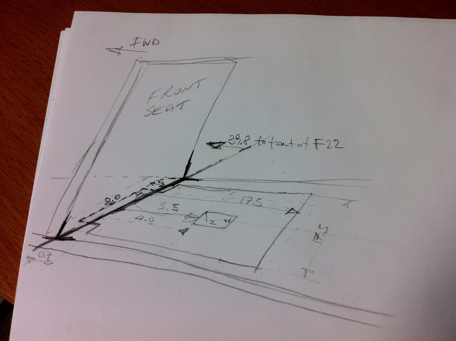
First on the list was converting all the mumbo-jumbo in the plans into an actionable sketch. 


It all make sense now, I think!


I must point out that my landing brake will end up 2” (5.08 cm) ahead of its normal position, due to the fact that my front seat is 2” further forward than the plans call for. Furthermore because my fuselage is also 2" wider, other EZs measurements might be a little different than mine, like the distance to the front of F-22 for example.

The next step was to transfer these measurements to the actual fuselage.


"Measure twice, draw once!"


Even as careful as I was, I was still able to mess it up. Fortunately, I caught the small mistake before glassing the fuselage.


"Ok, draw twice!"


Packing or duct tape is placed over the landing brake, and since fiberglass will not permanently stick to the tape, I will be able to cut and remove it in that area after the outer fuselage is glassed and cured, at which point the task of actually building the landing brake will begin.


Applying fiberglass release material (aka packing tape)

Tape cut to size with a razor blade

Mmmm... that nose gear hole is not very symmetric. I'll have to fix that!


In preparation for glassing the outer fuselage, and to help make this long layup less difficult than it has to be, I have built a few more aids with my limited carpentry skills.

First on the list is a way to rotate the fuselage ±45˚ along its longitudinal axis. This requirement is actually spelled out in the plans. 

So, I modified my saw horses for the task to come.


Rea hinge mechanism

Front hinge

Piglet ready for roasting!

Initially only half of the fuselage is glassed. 

Still fairly wet after curing for a couple of hours, but to the point that the cloth will no longer fall off as the fuselage is rotated to the other side, the opposite side is glassed. 

Although one or two helpers would be advisable, this layup can and has been done solo, and that’s probably how I will do it as well.


Carrying big pieces of fiberglass from my cutting table to the fuselage without disrupting the weave, would have likely been impossible on my own, so I repurposed some previously used 2x4s, and made a mobile stand for the UNI. 


Mobile UNI dispenser


This stand will be dragged around the fuselage as needed in order to dispense the cloth.