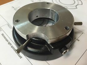
Spindle light
When my talented friend Phil talks to me about his ideas, I listen carefully, and when he told me about a microscope LED light on eBay that might work as a spindle light, I easily parted with $20.
 |
| LED microscope light |
The light turned out to be very bright, and that’s a great thing since I’ve often been forced to hold on to a flashlight while milling. It might be because of the mill's location, or perhaps the partition I erected to keep swarf at bay, but my setup has not been the best as far as ability to see what's going on.
Until now… that is if I could figure out a way to attach it to the mill. See, the root of the word "spindle" is… spin (duh!), and since it does spin, this makes it impossible to attach a light directly to the spindle itself.
After spending a little time looking up to the mill’s head from below, I had the idea of replacing one of its plastic cover with an aluminum piece that would be be concentric with the spindle, serve as a mount for the light, and not interfere with the spindle rotation.
 |
| Plastic cover |
 |
| Plastic cover original position |
 |
| Mill's head with the plastic cover removed |
After reverse engineering the plastic cover, as well as the microscope light, I came up with a drawing of the proposed mount made with Fusion 360.
 |
| Approximate dimensions for the MicroMark mini-mill |
Now, these dimensions are the best I could come up with while working upside down with a caliper, but should be close enough to make it work.
During a lull in my fiberglassing activity, I got on with the latest mill improvement.
Machining the spindle light mount
Unfortunately, I did have some issue with the mill. Because I still haven’t wired the limit switches, I might have accidentally over-traveled the X axis just before this job, and possibly dropped a few ball bearings from the ball-nut, as a result my milling of circles was off by as much as 0.040” (1 mm). Crap!
Luckily for me, this piece will never be seen again after today, and with the the location of the holes being the only critical part of the design, I quickly ran it by the lathe to make the mount round again.
 |
| Not pretty but it fits, and that's all it matters. |
 |
| The spindle is unaffected by the mount |
The light fit snugly on the mount. Thumb screws were not necessary except to prevent possible sliding movement due to vibrations.
 |
| Nearly a press fit, the light easily stays on without screws. |
 |
| Light on the mount, but off the mill. |
 |
| Back side |
So, I ended up radially drilling (#40) and tapping (3-0.5 metric) three holes into the aluminum mount to match the thumb screw locations.
 |
| As I said, this is just a light mount, let's not get overly complicated here. |
 |
| Smallest metric tap I have |
 |
| Three holes drilled and tapped |
 |
| Assembly side view |
Obviously, one would not want the screws to protrude through the mount and end up rubbing the spindle, so I made sure to stop when I saw the end of the tapered tap reach the inner diameter of the mount. This ensured the screws would be confined to the mount itself at all times.
 | |
|
Tool changes are still as easy to do as they were prior to the modification.
 |
| Spindle light is up and out of the way |
Overall I am very pleased with the results of this upgrade.
 |
| I might need sunglasses now |
Though I was concerned that the tool would cast a shadow right over the part to be cut, this turned out not to be the case. The whole cutting area is now flooded with so much bright light that I can even see what I’m doing now!
 |
| No tool shadows present within the work envelope |
UPDATE:
It turned out that the lack of precision was due to a bolt that loosened up due to the vibrations that occurred when I took full depth of cut passes. The bolt in question snugs the Y ball-nut to the table, and after tightening it the problem disappeared entirely.
Here are the latest backlash numbers...
 |
| No issues here! |

No comments:
Post a Comment