Viewing options:

Friday, January 30, 2015

Nose and nose gear - part 18

The endless nose (6.7 hrs)

She has been looking at me with those sad puppy eyes for sometime now, promising a relaxing break from the hard work and long hours I have not spent with her. I just fell for it, and went back to the her side. Nothing fancy this time, just a whole lot of rhythmic grunt work, and the pleasure of a deep body exercise.

Hey, wait a minute there! I was talking about sanding the Long EZ!

All right now, back from The Far Side...

First order of the day was to flip the fuselage. This is easier said than done. So, I decided to remove the main gear to lighten up the load.


Getting her ready to go belly up

This thing is a lot heavier than one would imagine


I swore I’d never take that off again, but I had to concede that I could no longer handle it all by myself, so the gear had to come off. 

The reason I hate doing that is that the gear was basically fitted in place, and it is very tight (as it should be) in its brackets. Removing it causes the steel bushings in the gear to scrape the aluminum bracket as the gear gets ever so slightly out of square. I really don’t know what to do about that, other than not removing it.


This just breaks my heart

More scraping on the right side


With the fuselage finally upside down, I could attend to some overdue matters. One thing I wanted to work on was to reduce the gap from the top end of the nose gear leg to the nose bulkhead just in front of it.


I know there are bigger holes in the nose, but today we are working on the small one.

The gap is a little over an inch (2.5 cm)


This gap could provide a lot of unwanted ventilation to my legs on those cold winter days, and had to be made smaller. 

I cut a piece of foam the size of the opening, and whittled it down to a shape that did not obstruct the nose gear movement.


When it's foam cutting time, it's hard to beat a table saw.

Any questions?

I used pins as depth gauges

Here the pins are holding the foam at the proper height


In order to proceed any further, the nose gear had to go, Luckily this time, working upside down turned out to be quite relaxing.


I wish this was always the case


I prepared some slurry for the foam, and some dry micro to take up small gaps, and bonded the foam piece to the bulkhead.


NG30 cam

Foam block glued to the bulkhead

Same thing, but viewed from the nose.


This piece of foam really hated its position, so I loosely reinstalled the nose gear, and stuck another foam wedge in the now smaller gap, to keep the former from wandering around.


Convincing the foam to stay in place


Because of the looseness of the setup, I chose to glass this foam piece after it was securely bonded to the bulkhead, to minimize fiberglassing drama.

While I waited on the cure, I decided to do a few more housekeeping chores. First on the list was to shape the walls of the battery compartment to be a little more concave. This took a lot longer than I thought it would have.


It looks a bit coarse at this stage, but it did smooth out in the end.

I neglected taking a shot after smoothing the surface, because the light didn’t allow for much depth perception, and it just looked flat, but you’ll be able to tell after I glass the foam.

Bored with the still loose foam wedge, I started picking my nose.
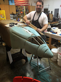

The foam dust on the ground should fill a multi-hour hourglass


Not that it needed to be shaped right then, but I figured I’d keep the back pain to a manageable level if I did a little every now and then. So, I sanded, and sanded, and sanded, and… you get the picture.

At the cost of sounding repetitive, I have to say that the blue PVC foam is a lot tougher to go through than the original Urethane foam the designer called for in the plans, but just as I did with the speedbrake, I changed to the blue foam because of strength and delamination issues with the Urethane. 

As a matter of fact I still have a stack of Urethane foam in the shop (I bought it when I was young and naive) that will never go in the plane.

Anyway, many hours later, one side of the nose started to look more like it should, though a lot more shaping is in the cards for it.
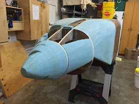

Still moving forward


Sunday, January 25, 2015

EZ shop trailer

Behind the scenes...


Friday, January 23, 2015

Anodizing - part 5

The sweet taste of success

"Awesomeeee!!!"


This might be the first time that I start a post with a photo. Pardon the excitement.

What has changed since last time’s failure, you might ask... not very much, as my data below shows.


Keeping track of the variables is vital. The "set" and "got" temps are due to the lengthened thermocouple leads.

The blame for the “orange disaster” rests squarely on my shoulders, for not taking the time to clean up the part as I should have.

This time I consulted with a chemical engineer (my daughter again), who knows a thing or two about adhesion between layers of gold 2 microns thick, photoresist, and silicon wafers (she’s into nanotechnology). 

Beside the need for a humidity controlled cleanroom (does my heater/AC count?), and the absolute necessity for dry nitrogen (damn, I just ran out of it!), her main message was to clean the part like I was about to have open heart surgery, and dry it well before the dye bath.

So, I did.

First, I washed the bracket with soap and water (twice) in the sink…


Cleaning all machining oil residues off of the part

… then I air dried it with compressed air (not so dry, I know), and cleaned it with Acetone…


This should remove anything still clinging on to the bracket

… I air dried it again, scrubbed it once more with Isopropyl alcohol, then air dried it again…


I used alcohol to clean any trace of acetone

… and yes, the toothbrush got air dried also, in between each treatment.

I then went through the same protocol as last time, and I didn’t notice any differences. The part came out of the dye bath looking like a million dollars, just like the failed one did before.


When the parts first come out of the dye bucket they are just incredible


I rinsed it again with distilled water, then dunked it in the boiling sealer, as usual.

Thirty minutes later, out she came. I rinsed it again in distilled water, dried it with compressed air, and… I was afraid to touch it, for fear the color would rub off… but it didn’t!

Success at last!


Not as shiny as when it was wet, but still wicked looking.

I am very happy with these results

The new bracket next to the failed one


I should also add that I probably changed 1/2 a dozen sets of nitrile gloves, trying not to contaminate the bracket again.

Was it all worth the trouble, and the cost?

“OH MAN IT WAS!!!”


Wednesday, January 21, 2015

Anodizing - part 4

Partial success… or partial failure?

This has been a very long day, made even more stressful by handling gallons and gallons of acids and other toxic substances. In the end however, it was well worth the effort, even though the part did not come out as intended.

I learned a lot today, and I was glad to have solved most of the logistical issues in the past few days, using a bucket of tap water, or it would have been really challenging trying not to spill anything.

But let’s start at the beginning…

This morning I mixed all the acids, dyes, and other nasty chemicals in their respective buckets, then warmed each one up to its nominal temperature. It turned out to be a very good thing to do, because a few unexpected things occurred. 

The PID box started heating up, after running the heater in all 6 buckets. I had the feeling this could happen, but so far it hadn’t been an issue in the limited testing I had done. I should have cut some slots in the box anyway, and now I will, but for the time being I just opened the box, and ran it that way.

The last thing I did yesterday, was to lengthen the thermocouple cables by splicing in a couple of feet of 22 gauge wire. I did this to gain some flexibility with the placement of the PID enclosure on the table. This had a strange side effect though, causing it to read 30 to 50℉ higher. Apparently the thermocouples are calibrated with a certain wire length, and making the leads longer screwed things up. 

In order to get 140℉, I’d have to set the PID to 170℉, and 197℉ was reached using 245℉. Not a really big deal, but another variable to have to juggle. 


Heating up the orange dye

Bringing the sulphuric acid up to temperature


To begin the process, I took one of the rejected brake brackets off the shelf, hooked it up to a titanium wire, and dunked it in the 130℉ degreaser for 5 minutes. I should have probably have spent some time cleaning it up beforehand, but I thought the hot degreaser might just be enough.


Degreasing the part


After 3 minutes in the de-smut solution at 100℉, I moved on to the actual anodizing at 71℉.


Anodizing has started, evidenced by the bubbles on the lead plate.


Given the amount of surface of the part, the online anodizing calculator suggested 2 amps for 2 hours.


This makes it easy


I had a bit of trouble getting a steady current, until I figured out that I needed a better connection with the titanium wire, after that it worked great.


I don't know about the volts, but the amps are right where I need them to be.


Two hours later I took the part out of the sulphuric acid, rinsed it thoroughly in distilled water, dunked it in the 140℉ golden orange dye, and three minutes later, the part looked like a million bucks.


This part looks amazing already

This color is so nice, I couldn't stop staring at the it.


Man, it looked awesome!

I was ecstatic at the color, that is until I took the bracket out of the 197℉ sealer. The part was in the sealer for 30 minutes, but after coming out and air drying, instead of looking great, it just looked a little dull.

I took a microfiber cloth, and tried to polish the bracket, but the color started rubbing off!

That wasn’t supposed to happen!

I’m not really sure what caused it. I know that the part was not clean before the degrease immersion, so perhaps this was the reason, but I won’t be sure until test #2.

Anyhow… on with the pictures of the semi-successful, or semi-failed anodized part.


The micro cloth rubbed the color off


Tuesday, January 20, 2015

Anodizing - part 3

Tying up a few loose ends

Being able to control the water temperature at will in the test bucket has been a satisfying success. It came however with strings attached, since I have had to manually stir the water in order to mix the cold lower layers, with the hot top layers.

I was a little surprised at the magnitude of this temperature extremes, reaching at times over 100℉ (38℃), and have been thinking about ways to overcome such temperature distribution ever since.

First though, I needed to address the temporary R&D nature of the heating assembly, by finalizing the design, and securing its components in an appropriate enclosure.


8" x 8" x 4" ( 20 x 20 x 10 cm) plastic junction box

Cutting the tabs off the electric outlets

installing two 240v outlets

PID getting wired


PID enclosure update


Back to the temperature issue... I have decided to go with an air injection setup, where PVC pipes would create an air distribution manifold capable of delivering pressurized air (2 psi) to the bottom of the bucket. I decided to call this a “bubbler” for lack of a more descriptive name. 

Anyway, the air coming out of the holes in the manifold should in theory provide enough water agitation to equalize the temperature. If this were to work, it would eliminate the need to reach in the acid with some device to stir it, and prevent it from dripping all over, as I reach in and out of the bucket.

Full of good ideas, I headed to Lowes to pick up some supplies, and begun assembling the “proof of concept” bubbler number one.


Air manifold prototype

Drilling 1/16" (1.6 mm) holes in the PVC pipes


Testing of the design in the water bucket proved very successful, with water temperatures consistently uniform throughout the entire range necessary for anodizing.


Testing the bubbler in water

The bubbler is agitating the water thoroughly.

Much improved temperature distribution


Bucket bubbler testing


I designed the bubblers to remain in their respective buckets at all times, including storage, in order to prevent accidental spills. The quick disconnect fitting at the top of the PVC manifold is still a few inches above the level of the acid at the 4 gallons mark, but low enough that the Gamma Seal lids can still close, and seal the buckets with their dangerous contents.

One of the unexpected issues that was highlighted in the test was that of the hose weight. The hose is so heavy that it tilted the bubbler over, if not restrained.

To counter that, I put together more PVC tubes in the form of an upside down U, with a quick disconnect on one side, a swivel connector on the other, and a 0-20 psi regulator in the middle.


Low pressure regulator with swivel connector

Small PVC stub is helping to stabilize the manifold

Swivel quick disconnect allows the air hose to lay naturally


This redesign completely addressed the previous shortcoming, so I happily moved on to reproducing the bubbler five more times, one for each bucket.


"I'm starting to detect a pattern here!"

Bubblers permanently installed in each bucket

Brass fitting above the acid, but below the level of the lid.


One last small modification I made was to the “fishing pole” parts holder design. I dropped the center section about a half inch (1.2 cm) to make some room over the top for a lid. 


A quick revision to the part holder

It looks like an apocalyptic steel scorpion from Terminator 15