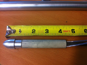
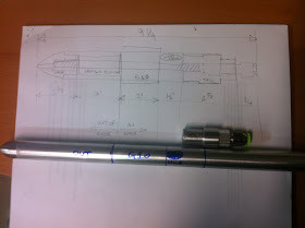
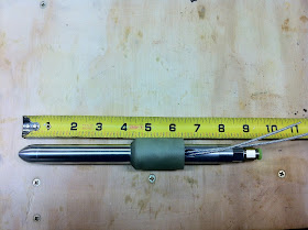
For those unfamiliar, let’s just say that the Pitot tube will sit on the nose of the plane and capture the incoming air pressure. Since this dynamic pressure relates directly to the speed of the plane, a flexible hose will connect the Pitot tube to the anemometer (air speed indicator), which in turn will display how fast the airplane is flying through the air. The airspeed indicator will also connect to the static ports, but that's a topic for another time (more on it here).
Although flying into icing condition is to be avoided at all costs due to its many cumulative negative effects, flying in the clouds is the first ingredient for an unintentional encounter with ice.
Ice forming on the Pitot probe, and obstructing the hole through which the air pressure is sensed, would render the anemometer useless. One very effective way to combat this undesirable situation is to heat the probe from the inside, so I set out to build myself a heated Pitot tube, borrowing generously from other designs I found online.
Ice forming on the Pitot probe, and obstructing the hole through which the air pressure is sensed, would render the anemometer useless. One very effective way to combat this undesirable situation is to heat the probe from the inside, so I set out to build myself a heated Pitot tube, borrowing generously from other designs I found online.
Brainstorming with my friends Mike and Wade was very helpful, and allowed me to explore many ideas I wouldn’t have thought of by myself. They in turn got excited about what I was trying to do, and expressed interest in having one as well, and in the end I decided to make not one, but three.
Pitot number 1 will go to Mike, since he’s at the stage in his build where he can install it. The pictures and dimensions in this post are those of the tube I designed for him.
I ordered the aluminum tubes and rod...
 |
| Raw material |
... and the G10 phenolic heat insulating material, and went to work. For the record, I was trying to upgrade to G11, which is rated to 500℃, but I would have had to order $500 worth. So, G10 it was!
 |
| G10 insulator |
I started working on the front piece first, using a tool called Ball and Radius Turning Tool.
 |
| Shaping the nose cone |
Overall it turned out pretty much like I had envisioned it in CAD.
Nose cone 3D presentation
 |
| Installed on the outer tube |
Next, I set to work on the back piece, and decided to mill 6 flats on it. This feature will allow me to tighten the finished Pitot using a 15 mm wrench, as well as tighten the quick release fitting using an additional wrench.
Tail piece 3D presentation
 |
| Mill setup for creating the bolt-like pattern on the end piece |
 |
| First 2 faces milled |
 |
| All 6 faces milled, and through hole drilled |
 |
| Testing for size |
The small hole was enlarged and tapped (NPT 1/8 - 27), and a quick release vacuum fitting installed.
 |
| Back piece ready for mounting |
 |
| Installed on the outer tube |
This is my first time working on a 0.75” (1.9 cm) aluminum tube of such length, as well as with the 1.25" (3.2 cm) thick G10 insulator, and I needed to update my lathe to a bigger chuck.
So, I replaced my 3" chuck with this 5" monster!
 |
| This is a BIG upgrade to my little lathe |
 |
| Chuck completely disassembled and cleaned up |
 |
| Spindle hole in plain sight (old chuck removed) |
 |
| New chuck in place |
The new chuck, with its bigger through hole, allowed me to shove a whole foot of tubing through the spindle hole, and out the other side of the machine, enabling me to work on one end of the tube with much greater setup rigidity.
First thing I used it for was boring the outer tube by about 10/1000" (0.025 mm), to a depth of 3.5" (8.9 cm). This created a cylindrical receptacle to house and retain the heating element in the very front of the tube, while allowing it to slide in and out easily.
 |
| Boring bar enlarging the hole |
Later I chucked the inner tube, brought it down to the proper length, and cut threads on both ends (1/4-28).
 |
| Forming the threads on the inner tube |
 |
| 1/4 - 28 thread |
 |
| Testing the threads with the nose piece |
Although the G10 is there to protect the nose cone from excessive heat, keeping the heating element outside of the nose altogether seems like a better idea.
The amount of Pitot tube that will remain outside of the airplane nose structure, being cooled down by the airflow, is predetermined by the size of the Pitot nose piece, plus the heating element.
The amount of Pitot tube that will remain outside of the airplane nose structure, being cooled down by the airflow, is predetermined by the size of the Pitot nose piece, plus the heating element.
 |
| Amount of Pitot tube to keep out of the airplane's nose |
The last major operation to perform on the outer tube was milling a slot for the wires.
How to align the spindle axis with the tube axis
 |
| 1/4" mill ready to cut the slot |
 |
| Wire slot milled |
So, here is a sketch of the master plan...
 |
| Basic layout |
... and the finished Pitot tube.
 |
| Finished Pitot |
 |
| A view from the front of the airplane |
 |
| As seen from inside the nose cone |
 |
| 6.14 oz (174 gr) including G10 insulator, 4.44 oz (125 gr) without. |
Here are all the components of the heated probe together.
Disassembling the Pitot
 |
| Heated Pitot tube components |
The only thing left to do was an operational check, to make sure it worked.
Testing the heated Pitot tube
As you can see in the video lack of heat is certainly not an issue. On the contrary, the voltage might need to be stepped down some, in order to be able to control the temperature, which was increasing rapidly.
I'm thinking a 3 way switch with OFF, LOW, and HIGH settings perhaps, but more testing is in order. At the very least, I have to find out how hot the probe really gets, and I will definitely need a better thermometer for that.
Testing the heating element
Further increasing the speed is not an option, and and even if I could, it would rapidly become counterproductive since at speeds above 250 kts friction raises the surface temperature by roughly 1℃ every additional 10 kts. I take advantage of this effect often at work, to manage the fuel temperatures of Jet A when it gets close to reaching the freezing point (-41℃).
The element is obviously putting out excessive heat. I need to find a final solution to this problem, and it is going to be an electrical one.
Meanwhile, Mike has received his tube, and he seems really pleased of how it has turned out.
 |
| If that is not a happy face, I don't know what is! |
 |
| The big picture |
 |
| Nose detail |
I will be working on Wade's Pitot tube next. His might be slightly different, as he is interested in making it retractable while parked, to prevent people from accidentally stepping or tripping on it.
.JPG)
.JPG)


Very cool! Nice machine work.
ReplyDeleteThanks, I'm really happy about the way it turned out.
ReplyDeleteWhere did you get the heating element? Could you use a 24V element as that would get way less hot when using 12V. Only 25% of the power.
ReplyDeleteI just checked the website I bought it from, and it's no longer valid. However, the unit is a regular Cessna element, so it should be pretty easy to find. I don't think going for a 24V unit would be a great advantage, as one still needs to be able to control the amount of heat (watts) being delivered via some kind of black box. Going 24V just present a different set of issues in my opinion.
ReplyDelete