Viewing options:

Sunday, May 26, 2013

Ch 17 - Pitch & roll trim - part 1


Roll trim components (4.1 hrs)

I’m getting a little out of sequence here, but I had promised my friend Wade I’d be making him two of the roll trim components.

The process was pretty straight forward, if not for the fact that I had to work with 0.049” (1.25 mm) thick 4130 steel, instead of  the usual aluminum.


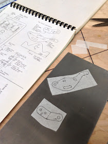
Reproducing the patterns

Patterns glued to the steel plate

Drilling the holes

All holes drilled

Trimming  the excess steel

Roughing out the shape with the band saw

Milling the slot

All major features completed

Duplicating the small bracket

With the matching oles drilled, the parts were secured, machining blue applied, and the outline scribed.

Outline scribed onto the machining blue

Major parts finished

Bending the bracket on the press

V block providing for the 90˚ 

Bent bracket

Parts completed and in place

Aileron trim brackets in position on the plans


Thursday, May 23, 2013

Landing brake - part 3


Glassing the inner brake surface (13.1 hrs)

The brake surface cured overnight to a tough outer shell, and while it looks pretty flat, I still needed to preserve whatever minimal contour there was, in an effort to produce a better fitting part.

The way that’s done, is by attaching 2x4s to it with Bondo.


Bondo drying


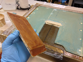
Once the Bondo set, I inserted a gasket scraper beneath the cured fiberglass, and easily lifted the speed-brake out of its depression.


Landing brake peeled off of the fuselage


As expected, a few pieces of foam broke off where the 5 minutes epoxy had been used to secure it in place for glassing. These holes will later be filled in with foam, dry micro, or both depending on the size of the crater left behind. Most of mine were small, so I ended up using just micro in all but 2 of them.


Some foam left on the fuselage!


The modeling clay I had used to seal the gap between the fuselage and the foam core, came off easily using the gasket scraper.


Removing the modeling clay


The only problem I had with it, is the oily residue it left behind. Not a good thing when you are trying to prep the surfaces for a structural bond.


Greasy film left where the clay once was


Perhaps the modeling clay that hardens might be a better solution for this purpose.

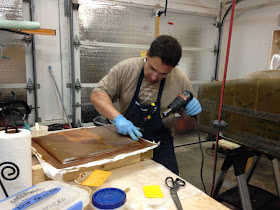
I took the assembly out in the front yard, and gave it a good scrub with a sponge dipped in water and dish soap. Although this seemed to do the trick, I also sanded it down to make sure I would not have problems with delamination.

Back indoors, I cut a hinge section to size, and trimmed it to clear all obstructions.


Roughing out a hinge for the brake


I also Alodined it to prevent corrosion, since this is an exposed part that is likely to pick up a fair amount of contamination. I think my Alodine must be getting weaker, because I’m having to leave the parts in the solution twice as long, and the results are not as good as they once used to be. At $75 a bottle, I’ll have to consider whether it’s worth continuing to purchase it, over just using the regular primer.


Adding corrosion protection to the hinge


At this point I had to cut away “enough” material to make room for an oversized wooden insert (CP#42 “builder’s hints”, where else!).


Cross-section of the hinged portion of the landing brake


When instructions start containing more and more words like "enough" or "as needed", and less and less dimensions, that's where science gives way to art, and by then you know... you are really on your own!

I started cutting the foam where I thought the plywood should go...


Adding a recess for the plywood insert

This gasket scraper really worked well at scraping foam too


... and ended up removing too much, so I had to put some back in. Not a big deal really.


Test fitting all parts


One thing I was not satisfied with, was the smoothness of the transition between foam and fiberglass, so I used my Dremel tool to remove a triangle shaped section of foam all the way around the perimeter. This ended up later getting filled with flox, allowing me to ensure a structural, bubble free transition.


Groove for flox


One of the few things I wanted to avoid, was ending up with a hinge line that was not perpendicular to the fuselage centerline, but things were not easy to line up at this point, since there are an awful lot of curved surfaces, so I used a laser to check for proper alignment.


Finally, a good use for this old laser! I bought it years ago for another project, but never really used it.


Unfortunately, this would only get me so far, since the hinge needed to get moved a thousand more times between up until the time it eventually got floxed in. My solution was to drill a couple of holes through the hinge and the fiberglass underneath, and use two nails as “alignment pins”. This worked very well.


Making things up as I go!


I elected to remove half of the hinge, as well as the hinge pin, and put clear tape over the parts that I did not want to contaminate with flox and epoxy, then went to work glassing the landing brake.


Hinge getting floxed. Notice tape protecting the hinge-pin holes

This is where the "alignment nails" idea paid off

Plywood going in

Searching for air pockets

Landing brake ready for curing

Peel-ply added to the center section


Notice that the two alignment nails were still in place during the cure. When the fiberglass got to the semi-cured “chewing gum-like” state, I removed both nails, and the clear tape.


Tuesday, May 14, 2013

"Tooling up" - Mill's new belt drive


A faster and more reliable drive

I know it's probably not the most exciting of topics, but there's got to be at least one person out there who finds this interesting. 

So, in the spirit of documenting all I've done, this post is for you, and you know who you are!

Still reading? See, I told you!

Back on track... I had been tinkering with the belt drive conversion idea for sometime, and while I appreciated its advantages, I did not think it was strictly necessary for me at this time.

There were however those few improvements I was looking forward to: 

  • much quieter operation 
  • increased reliability by bypassing all plastic (yes, plastic) gears used inside the mill’s head 
  • more than doubling of the high speed to 4300 rpm, compared the original 2000 rpm


Little Machine Shop belt drive conversion kit #2560


I had seen a few before and after comparisons of noise levels online however, and I was not convinced. 

For one thing, the maximum amount of noise picked up by the microphone depends on the microphone itself, its proximity to the source, what it is attached to, the software running it, and how the gains are set up. Once the sound hits the "red zone", it doesn't matter how much louder things get, the sound just gets cut off.

So, because a sound is pretty loud on video doesn't mean that it is representative of the actual sound level. Indeed, most videos of this kind make it a point to highlight the fact that the belt drive is actually much quieter than it appears to be, and the gears are much louder then they sound on video.

Ultimately this point has to be taken on faith, unless one has seen a live before and after demonstration.

As far as the reliability issue is concerned, I had not had any problems with the mill (yet), although I did crack a plastic 80 tooth gear on the lathe, so I'm familiar with how fragile they can be. 

It is common knowledge among users of these kind of machines, that it is not a matter of if, but a matter of when the plastic head gears will break, so most people are quietly dreading the day when it will happen to them.


Mill's head taken apart revealing the drive train


To minimize this possibility, I have gotten accustomed to taking multiple light passes with my cutting implements. This does increase the time spent machining a part, and should improve the gear’s lifespan, but one can never know for sure.

The problem is not so much that replacement gears might be expensive, but that they require special pullers to take them out, and put them back in. There is also no place I know where one can buy them anymore, so they need to be manufactured at home before the mill (or lathe since they use the same gears) is down for maintenance.

The belt drive is such an improvement in this respect, because it has the ability to slip when overloaded, and replaced when needed without tools.

I didn’t find the speed increase argument compelling at the time, but it was something I wanted so that I could engrave parts in the future, like instrument panels, circuit boards, etc.

What precipitated my purchase, was the sudden availability of the kit online, and since this kit is constantly out of stock, I pounced on it.


What's in the box


Installation was simple, with the only issue being the hole for the spindle locking bar being a bit too tight. I just chucked the bar to the lathe, and turn the business hand down a few thousands. Easy!

The mill now is unbelievably quieter, no screeching plastic noises, just smoothness both in low and high gear.

I am very glad I did the conversion now.

New pulley and bracket in place

DC motor running a new pulley in lieu of the old gear

The new high gear selected

Installation completed

Spindle lock bar in position (used to change cutting implements)

End of spindle tool turned down on the lathe for better fit

Before photo...

... and after.

Another before...

...and after.

By the way, this mod is perfectly compatible with a possible future CNC conversion ;-)