Emergency Locator Transmitter
After the 1972 Alaska crash where U.S. Representative Hale Boggs and Nick Begich lost their lives, and the crash sire never found, Congress mandated the installation of ELTs in all US registered aircraft. These 121.5 MHz units were prone to false alarms though (97% of all activations), and they only went off in 27% of actual crashes (AOPA statistics).
 |
| The big idea |
When I flew as an Instructor Pilot and Designated Examiner for the Civil Air Patrol in the early 90's, I used to teach how to search for downed aircraft using grid search techniques and airborne ELT receivers. The standard equipment in use at the time was unlike the typical direction finder where a needle points to the transmitting station. The actual units installed in CAP planes back then had two tiny vertical needles, one for left/right deviation (DF), the other for signal strength. As the search progressed, careful manipulation of the sensitivity control, and deviation needle interpretation were necessary. Skill and experience were paramount, so we trained continuously.
 |
| Typical Direction Finder unit |
One particular night I was dispatched to search an area of about 25 x 25 nautical miles in the Arkansas hills after a “satellite hit”.
Back then, there used to be a few satellites capable of receiving 121.5 MHz ELT beacons, and crudely triangulate its position after a few orbits around the earth. Sadly these satellites were decommissioned in 2009. Newer satellites equipped with 406 MHz receivers have since been launched though, triggering a wave of ELT upgrades as a new mandate was introduced.
Back to the search…
It took the best of three hours to identify the “crash site” at night, over mountainous terrain, in the middle of nowhere. I was very proud of this accomplishment even when I was later told it had been the typical false alarm, this time at an unlighted private grass strip (ie uncharted and invisible to us from the air at night).
The point being that even with trained search and rescue on standby, good weather, proximity, and satellite triangulation, it would take at least half a day before any rescue operation could be mounted to find one’s wreck, and that’s a best case scenario.
Enter the 406 MHz ELT…
“This ain’t your father’s ELT! This baby is digital!”
“This ain’t your father’s ELT! This baby is digital!”
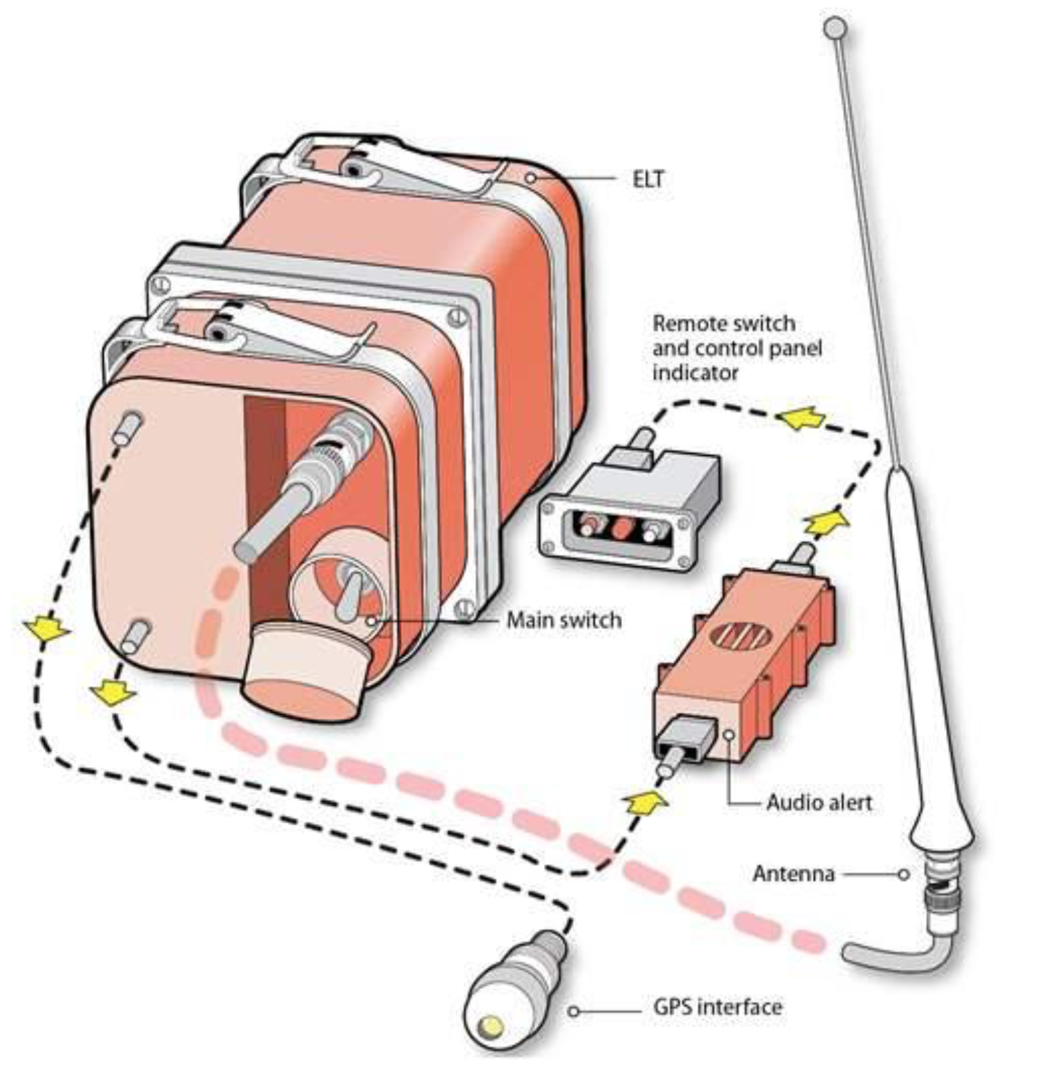 |
| 406 MHz ELT installation overview |
Sure, the frequency is now roughly four times higher, but more importantly the signal it sends contains encoded GPS coordinates and tail number to dedicated satellites, and it does so with 5 watts of power (hundred times more powerful than the older technology). This means that within moments of an accident, Search and Rescue facilities already know your name and exact location, and they can send someone to the exact crash site. No archaic ELT finder required (in ideal situations), no grid searches involved, and a lot less specialized training required, especially since the newer generation of direction finders makes the life of a search pilot much easier.
 |
| 406 Mhz with GPS seems like the way to go to me |
 |
| Latest generation of Direction Finders |
One always hopes to never to have to be in a situation where his life depends on the proper activation of an ELT, but at the cost of few hundred dollars, it is almost unthinkable not to equip.
JT had an ACK Technologies E-01 installed from day one, so I decided to replace it with the E-04. The 04 has the same external dimensions, and promised to be a straight swap.
 |
| New (left) vs old |
 |
| Looking mostly the same, if not for the additional GPS input wire. |
Best of all JT would be losing 1.5 lb (700 gr) since the new lithium battery is a lot lighter.
 |
| 1422 grams (3.14 lb) |
 | |
|
“What’s not to like!?”
For an extra $10 I purchased the full install version of the package, containing everything one needed for a new installation.
 | |
|
I started by disconnecting things that needed to be replaced, like a few wires, the old antenna, and the remote module.
 | |
The new unit comes with a speaker box that allows the pilot to hear when the ELT gets activated.
|
 |
| Speaker behind the instrument panel |
 |
| ELT moved 5" (13 cm) further back for marginally improved crashworthiness |
The E-04 transmits its signal regardless of whether a position is supplied by an onboard GPS or not. In the latter case the determination of the location is made a bit slower and to a couple of nautical miles of uncertainty. Still much better than the previous generation of ELTs, but the true power of the unit is realized when it is paired to a GPS locator, so I removed the canard and the instrument panel for this upgrade.
Luckily for me, the much smarter Marco that designed the instrument panel two years ago, not only left an opening for one additional circuit, but he also pre-wired it for power, in a bring-your-own-circuit-breaker-and-Dsub-connector type of deal.
Because removing the instrument panel is now only a five minute job, I was quickly elbow deep in electrical wires trying to determine the best way forward.
 |
| Back plate (aka Junction Box) opened exposing "wiring bundles" |
It turned out that all I had to do was install the 5 amps CB, and a Dsub in a spare hole, then run three short wires from my scrap-wire box from the new connector to the Garmin GNS480, then to power and ground.
 |
| Junction Box ELT E-04 new Dsub connector |
 |
| Glad I didn't throw these guys away two years ago |
 |
| Re-wiring this panel after adding new equipment is such an easy task |
That’s it! Wiring done!
 |
| Back of the Junction Box with the new ELT connector installed |
 |
| All I need to do now is connect the ELT Dsub to the actual ELT |
Unfortunately the E-04 comes with a weird micro-Din plug, so I had to fabricate an external harness to interface DIN to Dsub, not a big deal really, just a bit annoying having to solder on such tiny terminals with these old eyes.
 |
| Junction Box Dsub to ELT mini-Din connector wiring bundle |
A short time later, with panel and ELT wired up, I was ready to put everything back in the plane.
 |
| ELT CB only removes GPS data if pulled. ELT runs on its internal batteries. |
Everything, that is, except for the new antenna.
You see, the ELT instructions call for a 24" to 48” (0.6 to 1.2 m) diameter ground plane to be installed at the base of the antenna in order to help transmit a signal at full efficiency. Without a ground plane, the range at which a 121.5 ELT signal can be received would be severely diminished, making it harder to be located by rescuers.
Because the newer ELTs transmit on both 121.5 MHz as well as 406 MHz, I still needed to have a metal ground plane in the shape of a disc or, alternatively, four or more strips of copper (same material I used for the ILS antenna) in a radial pattern from the base of the antenna.
“But wait a minute… shouldn’t there be a ground plane already installed in the aircraft because of the old ELT?”
Well… yes, if one wanted to have optimal transmission in case of ELT activation.
Anyway, since the plane never crashed, and the ELT never went off… no harm no foul, but I am not taking any chances with this installation. Besides, it wouldn't seem right to go to all the trouble of buying and installing this satellite unit just to skip on the one item that could boost signal strength and help you get found quickly.
The question now is how to install such a sizable ground plane in the small nose of a Long EZ.
Talking to the makers of the ELT, it turns out that the ground plane could be further reduced to 14” diameter in order to better suit the 406 MHz signal, and since this is the direction the technology is going, and my best option for being found, I will opt for this easier to install smaller ground plane.
Talking to the makers of the ELT, it turns out that the ground plane could be further reduced to 14” diameter in order to better suit the 406 MHz signal, and since this is the direction the technology is going, and my best option for being found, I will opt for this easier to install smaller ground plane.
First thing to do was clearing everything out of the way, because this would be really tight quarters. Pretty hard not to make a bit of a mess in a situation like this, when even getting one’s arm down in there presents a challenge.
 |
| Original ELT antenna mounting point |
The easiest way I could come up with to visualize where the ground plane might fit was to make a mockup out of zip ties riveted together at the 7" mark.
 |
| ELT ground plane simulator |
This gave me the ability to play around with a physical object, and scout out the best installation configuration.
 |
| Ideally one wants the ground plane centered on the ELT antenna |
It quickly became obvious that the most rearward of the two brackets would have to go. One never really wants to reduce his mounting options, but since that one had never been used before, it was easy to give it up for a good cause.
 |
| "Sorry for having to tear down some of your nice work Terry! I'll try to reuse that somewhere else." |
 |
| Wheel well cleaned up |
 |
| Viewed from the left side of the plane |
With the unused bracket out of the way, coming up with a plan for the ground plane became more straight forward.
 |
| "This looks like it will work now!" |
 |
| Trying to keep the ground plane centered under the ELT antenna |
I decided I’d lay the antenna on the floor and cover it up with one layer of fiberglass in most places, perhaps two where my feet could reach.
“Let the sanding begin!”
 |
| Area sanded to a dull finish |
Meanwhile, construction of the ground plane began on the bench.
 |
| Copper tape is great, but extremely delicate. |
 |
| Ground plane elements soldered to each other |
 |
| Harvesting the shielding from a recycled wire |
 |
| Shielding soldered to the ground plane |
 |
| Shielding will connect to the antenna ground |
 |
| Soldered the shielding to a used washer |
 |
| Washer will provide electrical bonding with the ELT antenna |
Back to the plane...
Epoxy has the ability to transfer to places one never intended, so care had to be taken to cover up every surface one didn't want to accidentally contaminate.
Epoxy has the ability to transfer to places one never intended, so care had to be taken to cover up every surface one didn't want to accidentally contaminate.
 |
| Epoxy will get everywhere if one's not super careful |
 |
| Wouldn't wanna mess up that awesome paint job |
The very delicate copper foil was placed onto the floor of the nose, centered up right below where the actual antenna would go.
 |
| The copper tape is easy to rip. Fortunately one can use a small piece to bridge the gap. |
Then I started cutting up fiberglass scraps to go over it, making sure to leave the grounding wire above it all.
 |
| After a continuity test from the washer to the outer elements, it's glassing time. |
Eventually fiberglassing began.
Unfortunately, working in the 100ºF (38ºC) temperature, I experienced four exotherms in a row even using very small amounts of epoxy in the widest cups I had. This gummed up my last couple of brushes to the point they became unusable, and I had to finish up delivering epoxy from the cup to the cloth by dipping my gloved fingers in it, and stippling the glass.
Unfortunately, working in the 100ºF (38ºC) temperature, I experienced four exotherms in a row even using very small amounts of epoxy in the widest cups I had. This gummed up my last couple of brushes to the point they became unusable, and I had to finish up delivering epoxy from the cup to the cloth by dipping my gloved fingers in it, and stippling the glass.
I was definitely running in emergency mode at this point, but once you start glassing you cannot stop, or you risk having to scrap everything. In the heat of the moment (no pun intended) I opted for the slight epoxy mess over having to junk it all.
 |
| What a mess! Not one of my proudest moments, but got the bid tape down. |
I sure had some cleanup to do the next morning, but in the end it all came out well.
 |
| Took a long time to clean that up |
 |
| Ground plane is there to stay now |
 |
| Ground plane as seen from the left side of the nose |
After inserting new batteries into the remote and the speaker box, I entered the ten year expiration date into the airframe logbook.
 |
| Adding batteries to the cockpit remote control |
 |
| Battery added to speaker box behind the instrument panel |
Finally, I put the new antenna where the old one was, connected it to the ground plane first, and then to the ELT.
 |
| New antenna |
 |
| Ground plane electrically bonded to the antenna |
 |
| A static suppressor has to be attached between the antenna and the cable |
 |
| I'm planning on reusing that bracket for a possible remote Com #2 |
 |
| Bracket being used for cable management |
With the installation basically complete, the only thing left to do was register the ELT with NOAA, and test the system.
 |
| Had to dive pretty deep into the wiring there. Gonna be a bitch putting it all back! |
One of the tests consists of shaking the unit to see if it comes on as it should. The other uses pin #2 of the ELT’s Din plug and connects it to ground through an LED and a 300Ω resistor. If the LED light blinks, the ELT is properly receiving and processing data from the GPS.
 |
| ACK Technologies does not supply this, but looks like a pretty simple device to make. |
While this upgrade was a bit involved, I'd say that altogether it was not difficult, and totally worth it in my opinion.
I don’t consider the 406 MHz ELT a silver bullet by itself, but knowing how unreliable and limited the old type of emergency beacons are, this new technology is definitely a big step in the right direction, perhaps even more so when paired with a PLB (Personal Locator Beacon) to be worn on one’s person.
And while on the subject of Personal Locator Beacons, I will also be looking into them in the near future, and will talk about it right here as soon as I make a decision on a unit for myself.
“So... stay tuned!”
No comments:
Post a Comment