Chronicling my Long EZ construction (and a few other things).
Disclaimer
This blog is for entertainment purposes only, and is not meant to teach you how to build anything. The author is not responsible for any accident, injury, or loss that occurs as a result of reading this blog. Read this blog at your own risk.
“What’s it got to do with building a Long EZ?!”, you say.
You see, sometime in the life of a project the opportunity to score some easy points with one’sbetter halfpresents itself. These are almost as good as cash, and can be redeemed at a later date, for example when one would rather go flying than mowing the lawn.
So, when Gina suggested she should go buy a new blower because the old one could not be started, I caught the rebound and decided to score by showing how those pesky CNC machines I spent so much money on, could actually save us some cash this time.
Upon further examination, it turned out thepulley sheared some of its teeth for the second time in a few months.
Exploded view of the leaf blower
Plastic teeth on starting pulley
Obviously the plastic teeth are no match for the steel clutch fingers, so I thought I'd rebuild the darn thing out of metal.
Closeups of the damaged teeth
Another look at the damaged pulley
I started by recreating part of the clutch mechanism in CAD, as an insert to be installed into the plastic pulley.
Pulley insert
The insert would be made out of a 2.5” bar (6.3 cm) of 2024 aircraft grade aluminum.
Same stuff I use on the Long EZ
The busted clutch teeth had to be removed, and this was easily accomplished on the mini-lathe.
Removing the busted plastic teeth
Meanwhile, the mini-mill got in on the action too by machining the pulley’s new teeth.
Machining new teeth on the pulley insert
The insert’s fit and finish came out really nice, and the end-mill pattern on its surface was absolutely smooth.
Pulley prior to damaged teeth removal
Pulley with teeth removed and insert pressed into it
Pulley with insert
A better look at the new teeth
Rewinding the spring was a total pain, and it had to be done at least half a dozen times before I figured out how it really worked.
Upgraded pulley back in its place
Closeup of the starting assembly
Testing the action of the spring
At last the darn thing went back together again, and I could verify its operation.
Final leaf blower starting test
This was a pretty fun and challenging project that kept me busy on an actual rainy day.
Crisis averted, points collected, and payback on the horizon.
Truth is,if YOU needed one YOU most likely would know it by now. For the benefit of those who have never heard of such a thing, I will take the easy way out and just give you the basic idea here, because this subject can quickly become rather confusing.
ADS-B stands for Automatic Dependent Surveillance – Broadcast. The OUT stands for the required aircraft mounted transmitter, the IN for an optional receiver on board. We are basically talking about a new type of transponder ($$$) that integrates high precision GPS signals into its data stream for the purpose of enhanced ATC separation.
I think everyone would agree that separation between airplanes is super important, but ADS-B is expensive, and sort of mandatory (open a fresh can of worms here) so, settling on a unit that would offer the best bang for the buck took me quite some time. Coughing up big dollars for a fancy unit was not in the cards, as it would have been eating up all my gas money, providing separation services only between myself and my own airplane ☹️.
Needless to say, thanks to the FAA’s ADS-B mandate, come January 1 2020, access to certain types of airspace will become virtually impossible without an ADS-B transponder, so last Christmas I took advantage of an online $100 discount, and purchased a Trig TT22.
TT22 transponder and optional TC20 control head
In addition to that, since the FAA was still offering a $500 rebate to install it (subject to many hoops), I dropped everything else I was doing, and started working on that project.
I was not too happy to be forced to spend money to replace functional equipment I already had, but the $600 reduction to the price of entry sure softened the blow.
“Why Trig?” "Curious bunch aren’t you?!"
Alright, if you really want to know, price was important, but there were other considerations, such as the ability to fly internationally and above FL180 (no such plans at present time), resale value, removing old and heavy, failure prone boxes, with new light weight more reliable ones, remote mounting, more available panel space, etc.
Sure, the TT22 is a 1090MHz unit, but my existing antenna was already capable of working with it, saving me a few installation headaches. Beside, using my portable Stratus ADS-B IN (1090 and 978 MHz) I have already been displaying weather and some of the traffic on my iPhone/iPad for a few years and now, thanks to the OUT solution, the picture would become even more complete.
Dual band ADS-B IN plus wi-fi AHARS (Attitude Heading and Reference System) backup
With ADS-B IN alone, often there would be a lot more airplanes out there than on any of my screens, but adding my own OUT solution would make me more visible to others, and help me see a more complete traffic picture.
ADS-B OUT equipped planes appear with N numbers. ADS-B IN brings in weather info (blocky radar pic)
Before starting the installation I had to decide whether I wanted my Mini-AP EFIS to control the remote transponder, or use the optional TC20 control head supplied in the box. Initially I favored the first solution, because it cleaned up the panel, but after a practice flight where I pretended to change the squalk code using the EFIS buttons, I became convinced that the additional button pushes required on the Mini were not worth the savings in panel space, and that the TC20 control head would be much easier to manage.
This problem stems from the fact that the Mini has much fewer buttons and knobs to perform the same functions as its bigger brothers, like Wade's GRT Xr which sports three times that amount of hardware. Necessarily, some of the functions in the Mini are buried three level deep in the software menu structure, making the feature possible, though cumbersome.
GRT Mini-AP Transponder integration video
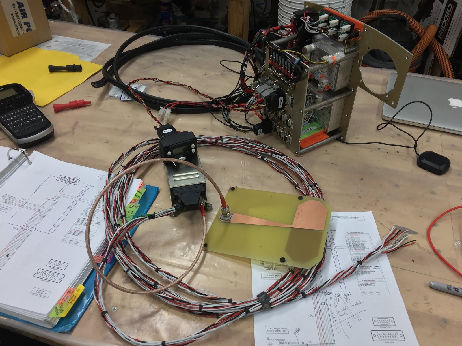
In the end I went with the TT22/TC20 combination, and began drawing the electrical schematics to support that decision. The required high precision WAAS GPS signal was provided by the GNS480 (I love that radio!), and all wiring had to be routed through the rear panel plate (aka Junction Box), even though that added a few extra wires and connectors. This was important in order to support the original instrument panel maintenance philosophy, and its ability to be removed as a unit.
My ADS-B OUT installation wiring going through the Junction Box
As always, with the purchase of any new equipment, the first question always is... “Where am I going to put this?”, followed by... “How is this going to connect?”.
After liberating the right strake from the big and heavy Wheelen strobe lights power supply, I fantasized about reusing this cavity for the ADS-B box, but I very much worried about having to get back in there for maintenance, as it would require the right wing removal. Not something one wants to do too often.
Former right strake occupant (bottom) vs new one
Nevertheless, the zero footprint of this installation was too enticing to not rationalize away, and plans for a new mount that reused the existing studs were drawn up, and a scrap of 2024 aluminum pressed back into service.
"I knew I had saved this piece of aluminum for something important!"
Marking the critical hole positions to match the studs left in the right strake after the Wheelen box removal
Dykem is a layout fluid used in the machining trade that dries up quickly after being brushed onto a surface
Dykem is easily scored with the tip of a caliper, or a scribe.
This should be self explanatory at this point
Proof that I can still make stuff by hand! 😂
"This is a lot more work than I remembered!"
Rounding corners. "Good thing I only need to make one!"
"Can't even drill on center anymore!" 😫
"Here we go at last!"
"That'll do!"
Bolts ground flush. Red Loctite will be used on nut treads.
"That's what I'm talking about!"
Adding corrosion protection
The adaptor plate fit perfectly, and for the time being I thought this part of the installation was over. That turned out not to be the case however, as you shall see shortly.
The critical hole spacing worked out
Test fitting with hardware
To answer the second question I carefully measured the wire run from the strake, down the hollow center-section spar, into the hell-hole (space behind the passenger seat), and down the left side of the fuselage all the way to the instrument panel, then I added another foot for good measure. Good thing I did because when I twisted the wires into a bundle, it lost about one foot in length. 😅
Making the 19 footer main wire bundle
Twisting it all together (not a requirement)
Tying the bundle every foot or so
What a finished bundle ready to use looks like
With the newly created harness on hand, I started populating the d-sub to the TT22 as from my diagram.
Pinning the d-sub
On the Junction Box, I installed two connectors, one for the TT22, the other for the TC20, and made super short connections between the two, right in the back of the plate following the schematics I drew up.
Added a connector for the TT22...
...and one for the TC20
Wiring can take over the entire shop if one's not careful 😱
At this point I could already start connecting most of the wires to the devices, except for one side of the main wire bundle that had to remain bare to be able to go through various holes and hidden passages, to finally resurface toward the front of the plane.
Had to leave one end open
Last but not least, was the construction of a short antenna cable. The plan was to move the antenna from the left strake to the right one and have the shortest coaxial cable run as possible.
ADS-B antenna in its original location on the left strake
I only use RG400 on my plane/s
TNC connector completed
TNC connector is an expensive fine thread screw-on type
Regular BNC connector to go on opposite side
Both connectors are installed the same way, starting with crimping the center contact.
The BNC body is then inserted under the shielding...
... and a sleeve slid over it.
The sleeve gets crimped
At this point the connector is functional
I always add a bit of heat shrink to finish it up
A finished TNC to BNC coaxial cable ready for use
Added coax and antenna
While working comfortably in my heated garage on the ADS-B (this was in January), I decided to take advantage of having the panel in front of me to do a few updates and repairs.
I 3D printed a shelf on which to mount the two Mini-AP’s GPS antennas, removing them and their wires from the nose of the plane.
New 3D printed platform
Mini's antennae permanently mounted
This eliminated the need to always remove antennae, their wires, and associated miscellaneous zip-ties every time I wanted to remove the instrument panel, a much needed improvement in the maintainability department.
Unfortunately, the last time I removed the panel, I accidentally cut one of the GPS antenna’s wires, while trying to cut one of the zip-ties, reinforcing in my mind the pressing need for this mod.
“Doh!”
Being a shielded coaxial cable, I had to think a little outside the box about how to perform this repair.
Center conductor soldered
Heat shrink to insulate the center conductor
Outer shielding soldered together
Scrap shielding to be soldered to the original shielding
After soldering the center conductors to each other, and putting heat shrink over them, I soldered an outer shielding scrap over the coax's own shielding, and heat shrunk a length of tubing over the whole thing. Not the prettiest thing to look at, but six months later the GPS is still working flawlessly.
Back at the hangar, while test fitting the wire bundle installation with the TT22, I realized that the unit needed to be moved further into the strake's cavity if I was to be able to mount the right wing back on, because the d-sub connector and the antenna wire stuck out of the strake a bit too much.
This meant I had to go back and make a longer mount for the transponder, and since it look like this might turn into an iterative process, I decided to draw it up in CAD once and for all, and use the new CNC plasma cutter to cut a sample piece out of junk steel and verify the new dimensions.
Testing the new CAD design cut on the CNC plasma cutter on scrap steel
"Looks long enough"
"I think it should work"
All looks well underneath. Time to cut the real one.
With the nod of approval from another test fitting session, I cut another bracket out of 2024 aluminum.
Aluminum (left) vs steel
Alodining it for corrosion resistance
"Those nuts are never coming off!"
Added dome baffle seal material to cut down on possible vibrations
Test fitting with hardware
With all wires and antennae hooked up, I began testing the installation.
TC20 in a mockup of the new panel (#4)
It's very rewarding when you throw the switch and things light up 😀
Some testing done with Epix Aviation's new toy
"I'd call that a win!"
Everything worked perfectly, until I pushed the short coaxial cable into the strake in order to properly mount the antenna. As soon as I did that the transponder signal was lost. It took me a few days, and a few emails to Trigs, to finally figure out what was happening. Initially I thought it was a minimum distance issue between antenna and TT22, instead it turned out that you are not supposed to coil the coax over the transponder box.
Coax cable looping over the TT22 as the antenna is pushed toward the strake
This meant that the planned new antenna location at the end of the right strake wouldn’t work, and that it would have to go back on the left strake, quadrupling the required length of coax cable. Stringing nearly nine feet of RG400 coax is at the upper limit of what is allowed in the installation manual, but it was my last option, short of going to a different antenna design.
To cut down on coax cable length, I bought a 90º screw connector ($$$$), reopened some of the holes that were used to drill the center-section spar 20 years ago (thanks for the intel Wade), and used one hole as coax pass-through, the other for the main wire bundle.
Going with a new, more expensive approach.
Hole through which the bottom spar/wing mounting tabs were match drilled
Top hole is the one through which the top spar/wing mounting tabs were match drilled
Holes covered by foam and glass, and were reopened to serve as wires pass-though
Protecting the surrounding space prior to adding micro
The micro will protect the exposed foam
With all the wires now having access to the hollow center-section spar, it was mostly an exercise in patience getting them to where they needed to go, then putting the wings back on, and fire up the Trig box.
Walter's 40 year old table I inherited at his passing (😢) still serving it's original purpose.
My long time friend and mentor Walter would be proud to know he's able to help a new generation of Canadians
This is panel #4 with the ADS-B OUT installed
Initial flight testing went very well, with Approach Control having no trouble seeing me for the entire 30 minutes required for me to be in their airspace to qualify for the $500 rebate. About a month later the Government check arrived in the mail and was promptly cashed.
Old KT76A transponder checking in at 3.3 lb!
Altitude encoder only weighed ⅓ lb
The final installation resulted in a total weight reduction of 2.6 lb (1.169 kg), at a price of around $550 for every pound lost 😬. "Take that Jenny Craig!"