“Will this dog hunt?”
Before I can answer this most important of questions, it’s time to give this baby exactly what she needs… clean, dry, oil free compressed air.
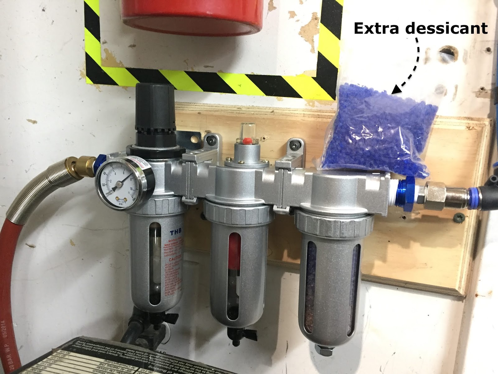
I purchased a particulate filter, pressure regulator, water trap, coalescing filter, and desiccant dryer combo for my air compressor from eBay for about $120. I liked the fact it was a metal and glass construction, and it was pretty inexpensive. True, I’ll have to bake the desiccant more often compared to a bigger unit, but I can live with that.
 |
| Search eBay for "filter regulator / desiccant dryer / coalescing filter" |
Next step was to assemble all the pieces of the plasma torch. It’s hard to convey how beefy and well put together this plasma cutter really looks and feels like. I guess this time you’ll just have to take my word for it, but trust me, this is one of the best units out there, and the benchmark against which all other plasma cutters are compared. Enough said!
 |
| Torch consumables |
 |
| Torch assembled |
With plenty of electricity and dry clean air, it was time to pull the trigger in the direction of some scrap steel at last.
 |
| First cut in steel (part flipped to show dross) |
“Wow, that was easy!”
As a second test of the unit, I decided to cut the top tray of my welder’s cart in half…
 |
| Welding cart minus top tray |
 |
| Tray sliced in half |
… then splice in some scrap steel to make it wide enough to hold both the TIG welder as well as the new plasma cutter, trying to alleviate the worsening problem of lack of space in the shop.
 |
| Had a few of these steel slat guides laying around gathering dust |
 |
| Rear of slat bent up to match rear of tray |
My welds sucked, but it was good practice on a piece nobody will ever see again.
 |
| Enlarged tray welded up and reinstalled on top of the welding cart |
One of these days I’ll get around to painting it black, but for now it’ll do just fine. The top shelf overhangs on the right side so that it is not in my way when I walk by the welding cart.
 |
| The width is just perfect for the two machines |
 |
| Left the tray overhang on the right side only |
 |
| The additional tray capacity is out of the way toward the wall during normal use |
So, now we have a working CNC table, and a working plasma cutter. Is there anything else left to do to mate the two?
There actually is the small detail of how to control the firing of the handheld torch from a computer program.
Because I bought the 45XP with the CPC port in the back, it is basically prewired for mechanized CNC operations. However, the handheld torch lacks the ability to respond to the computer controls. Since buying an additional mechanized plasma torch was not in the cards ($$$$), I employed a workaround some guy posted on the Langmuir forum.
This required changing the pin configuration inside the torch 's plug, and zip-tying the torch’s trigger in the ON position.
 |
| Torch's plug before and after (USE AT YOUR OWN RISK) |
Obviously, a number of safety devices are bypassed this way, and the torch is no longer able to be used by hand. That is not a problem for me due to my intended use, but you might want to make your own assessment of the implications and risks of doing such a thing.
The CPC port is on the back side of the machine.
 |
| Circular Plastic Connector (CPC) plug in the back of the plasma cutter |
Only two pins (#3 and #4) are used to communicate with the computer for firing the torch, and the order is not important.
 |
| Pins #3 and #4 control the firing function |
Once my CPC male plug came in, I put it together and permanently connected it to the machine.
 |
| What a shame, only two wires for such a big plug |
The other end of this two wires connects to the controller board.
 |
| CPC port pins #3 & #4 are wired to the Controller's torch on/off plug |
That’s it!
What do you say we find out the answer to the very first question of this blog post?
Scared the crap out of me! 😂
“That was awesome!”
So now we know it will work, but will it be good enough to cut instrument panel with any precision?
While I work behind the scenes trying to figure that one out, let’s have a little fun cutting things up…
 |
| Same flange cut at different speeds and amps. Note the different widths of the heat affected zones. |
 |
| I designed this part to check cut size accuracy. Note the wider heat affected zone of outside corners. |
 |
| Designed vs measured sizes |
 |
| Test cutting a second "Junction Box" in steel |
 |
| Another steel test cut... instrument panel version #3 duplicate |
 |
| It really seems to fit quite well |
 |
| Aluminum (left) and steel (right) brackets |
Now that we have this technology in the shop, let’s see if we can leverage it to do some useful work with it... next time.