General wiring and the junction box/plate
In the last episode I discussed how the plan is (for now) to bring all the individual wire bundles to a junction box/plate, then do the actual system interconnections on its back side.
Today I will finish the first version of this wiring, knowing full well that it will change soon for a few reasons, one… I’m sill missing the 429 ARINC module, two… I might not get all the functionality I need from this configuration, and three… I’ve never done this before, and I might just blow up the shop.
The first thing on my plate was providing a power supply to all devices used, and since this is commonly done through the use of a “bus bar”, I ordered one from SteinAir and started prepping it for panel installation. This was pretty straight forward since I had made the Circuit Breakers spacing to be 3/4” (19 mm), so all I needed to do was drill screw holes every 3/4” on the bus bar.
 |
| Drilling my new power distribution ba |
I bent the top end in order to clear the big 5A breaker/switch for the servo motors, and provide a way to connect to the existing Essential bus.
 |
| The circuit breakers will connect to the holes in the copper bar |
After shortening it a bit, I mounted it in place by screwing all Circuit breakers to it.
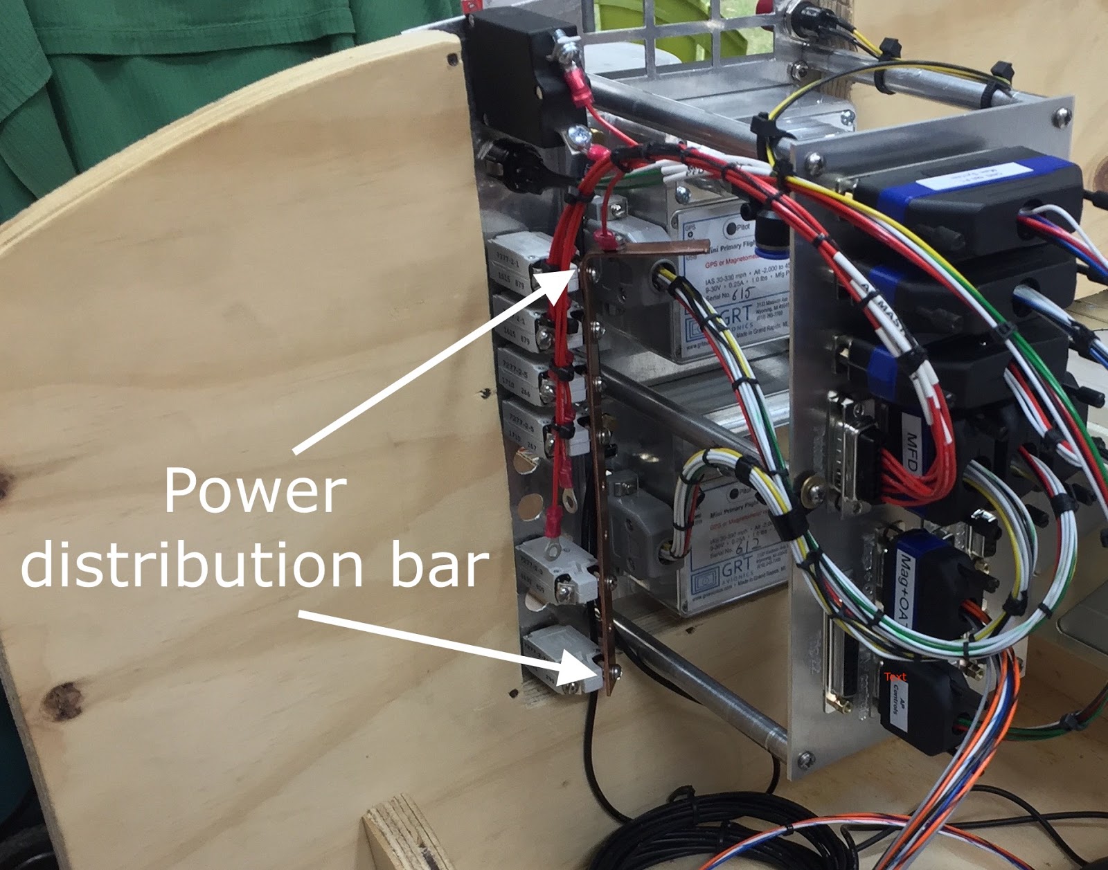 |
| New bus bar mounted |
When the existing Essential bus gets connected to the copper strip, all the CBs will receive power, and trip as necessary if a short or overload is detected within their respective domains.
The second thing I needed to make was a ground return path. I chose to tie all returning grounds together at the back of the junction box, in order to have only one wire exit the panel, and keep it more easily removable.
 |
| Ground return path being worked out |
 |
| All grounds will obviously be tied together here |
 |
| A ground bar is born |
 |
| Most of the wiring done (Yep! One pin at a time.) |
Now, all I’ve done so far is bringing in power and devices to the junction box, not actually connecting anything to anything else. The hard part will be doing the “smart wiring” inside the junction box (aka… behind the junction plate).
This obviously requires a lot of time spent on each device’s installation manual to understand what connects to what, why and how. I will spare you the learning curve and show you this intermediate diagram I drew up as my guide at this stage of the wiring…
 |
| Not the final version yet, but a good start. |
If you notice some resemblances to Wade Parton’s diagrams, it is because I’m trying to keep as much commonality as possible with his design in order to simplify possible diagnostic and troubleshooting. Since we both have at least one Mini EFIS, a GNS480, and a TT-22 transponder in common, this makes it easier for him to understand my design choices, and vice versa.
So, with the junction box/plate (JB) removed from the panel and flipped over, let’s start stringing wires based on my schematics.
 |
| Junction box/plate removed for initial wiring |
 |
| This is the actual brain of the operation |
 |
| I never said it would look orderly. Perhaps I should go back to the enclosed box concept. |
After finishing the main wiring of the plywood instrument panel, I did an initial power up test. The "magic smoke" remained inside the radios 😁, so all is well at this point.
Because GRT Avionics hadn't shipped the ARINC module yet, the radio was not able to communicate with the EFIS. Also, to keep things simple at this stage, Pitch and Roll servos were not plugged in yet, though the homemade junction box is already pre-wired for them.
Turning on the switch for the first time
The panel is now a huge step closer to the actual airplane installation, and a vindication of my junction box idea, which so far has performed flawlessly.
Of course none of this would have been possible without some "electrical mentoring" at a distance from Wade Parton, a lot of time digging through the many manuals, and asking “stupid questions”.
Ah, you are too kind Sir! Fun stuff all around of course! ;)
ReplyDelete