Disk brakes heat shields (25.2 hrs)
Last month I stopped by my friend Wade’s home to check out the incredible progress he’s making on his Long EZ project. We talked about airplanes and other stuff for so long that we ended up going to bed around 4 am.
CP#70 was one of the topics of the night. In it, on page 5, the issue of how to prevent heat damage to the gear legs from the disk brakes is discussed, and fixes are offered. The problem is addressed by venting the top of the wheel pant (when in the "grazing" position), wrapping the bottom of the leg in heat resistant fiberfrax, and by adding heat shields between the disks and the gear legs.
One of the things I literally took away from our get together, was Wade's paper template for the disk brake heat shields.
| Wade's heat shield template |
I have to admit it looked very clever, covering a greater portion of the disk surface than others I have seen in the past.
| Excellent disk coverage |
Not wanting to let a good idea go to waste, and with Wade's blessing, I set out to reproduce his design on the computer, and machine a set on the mini-mill. Obviously one could have accomplished this in many other ways, the best of all being a CNC plasma table, but you’ve got to work with what you have, so milling it would be.
Fist though, I’d have to extract some approximate dimensions from Wade’s drawing, then massage them a bit in order to create a symmetrical design. For this purpose, I dusted off my 37 years old drafting table, the same one my parents bought me in high school, and started analyzing Wade’s masterpiece.
| This drafting table is ancient, but still works great. |
| Extracting some approximate dimensions |
I used Fusion360 CAD on my MacBook to reproduce the heat shield, then print a 1:1 drawing of it for testing purposes.
| 1:1 drawing of the new and improved heat shield |
| This thing's got better coverage than Verizon! |
I wish I could say I nailed it the first time, but it actually took 4 revisions to come up with something I’d be willing to try on the mill. I will share the pdf with Wade's permission in the "Downloads" section of this blog.
| 3 of the 4 iterations |
One of the latest update was the slotted mounting holes. I did this to compensate for minor possible misalignment of the holes in the gear legs, since these were drilled by hand.
 |
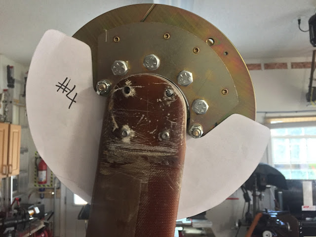
| Test fitting #4 |
 |
| #4 gets the nod of approval |
I ordered two 0.125” (2.3mm) thick 2024 aluminum sheets, but it looked like I would be able to squeeze both heat shields on one plate.
| This is going to be a tight fit |
My biggest problem was that these parts were twice the size of my mini-mill’s machinable area, a big problem indeed. I would have to think outside the box for this to work.
I decided to machine each shield with two separate operations, one would take care of the top half, the other would do the bottom contour. Each part would have to be repositioned between operations, so I created a fixture that would accommodate both ops, and make the milling accurate and repeatable.
| Brake shields fixture to be |
| Bolts for alignment and hold down use |
| Nearly final configuration of the fixture |
How well did it turn out?
Much better than doing it by hand of course, but not quite perfect, I’d say 95%.
I think a better way of doing it would have been to use dowel pins, but there was just not enough room on the plate, so I used the skinniest bolts I had, and ended up with ever so slight misalignment problems. Nothing that a quick pass on the belt sander couldn't fix, but not as exact as I had expected.
| This is how the top half would get machined |
| Plate moved to cut the bottom half |
| Heat shield bottom completed |
 |
| Two fully functional generation #4 heat shields |
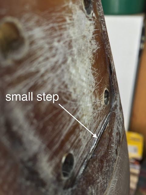
Mounting the heat shields on the gear legs uncovered a problem I had not anticipated, a fiberglass ridge had formed when I originally mounted the axles over wet fiberglass, and now the shields could not lay flat. On top of that, I needed additional clearance for the fiberfrax insulation that would eventually be wrapped around the bottom of the gear legs.
 |
| Two steps forward one step back |
 |
| The step is around 1/16" (1.6 mm) thick |
Wise old Wade anticipated this issues, and fabricated the shields first, than used them over the wet fiberglass, guaranteeing a flush fit.
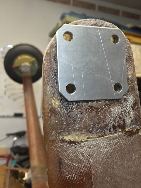
“Crap, I need axles spacers!” Back to the computerized drawing board…
 |
| Axles spacer design |
Actually making them turned out to be pretty easy using the leftover aluminum. I'll put the drawing in the "Download" section as well.
| You've got to love it when everything fits this tightly on the first try |
Fit turned out great and all clearance issues gone.
Of course, I couldn’t just mount bare aluminum to the only place on the plane that would encounter every single puddle I will ever taxi through.
With my Alodine too old to yield acceptable results, I decided to dust off my barely used 1 year old Anodizing setup, and finally get my money’s worth out that rig, but we'll talk about that on the next installment of the heat shields manufacturing story.
UPDATE: (4-29-16)
I decided to make the shields over again, and record the machining on camera. This time I used dowel pins to make the whole process more repeatable, and they actually came out great.
I have had some issues with the anodizing though, with one of the shields not taking the color as well as it should have. I believe it had to do with some corrosion build up on the "fishing pole" I use to suspend the parts in the acid, an electrical issue, since all parts went through the anodizing together.
I'll try to figure that out later, but since these parts are otherwise perfect, I will use them on the plane.
"Big game" on the X2!

