Making all the little bits (7.0 hrs)
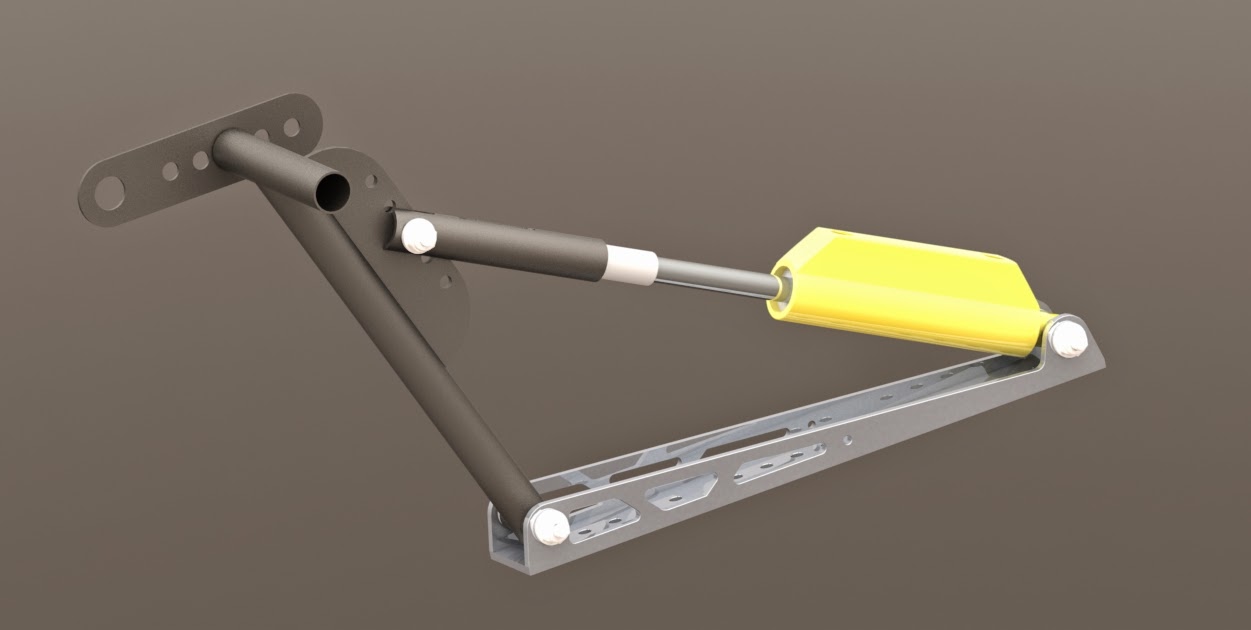
I really like the brake/rudder pedal design I came up with, and although actual use might eventually dictate small modifications, for the time being the EZ shop R&D department (Research and Development) has been shut down, while the Manufacturing branch is ramping up production of the system's components.
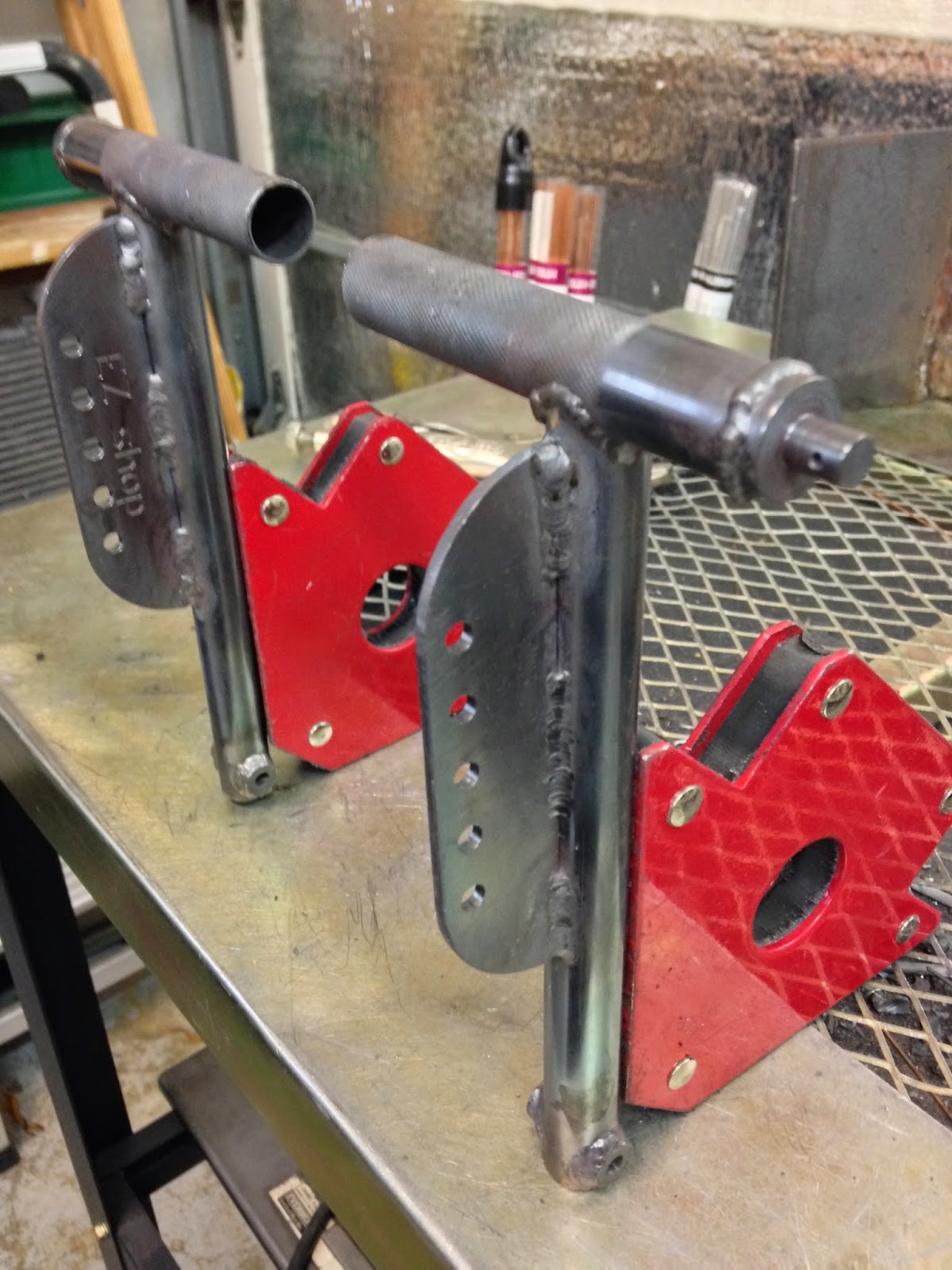
To maximize leg room in the nose, I had planned on mounting the brake assemblies as close to the outer sidewalls as possible, which means they would be at a roughly 12˚ angle with the airplane centerline. I had also decided to remove the F22 stubs that were part of the original brake design.
 |
| While it looks bigger in the photo, the angle is barely 12˚. |
One of the improvements I had considered, was to weld the top horizontal tube at a 12˚ angle to make it parallel to the bulkheads. This would prevent my feet from getting a little twisted while pressing the pedals.
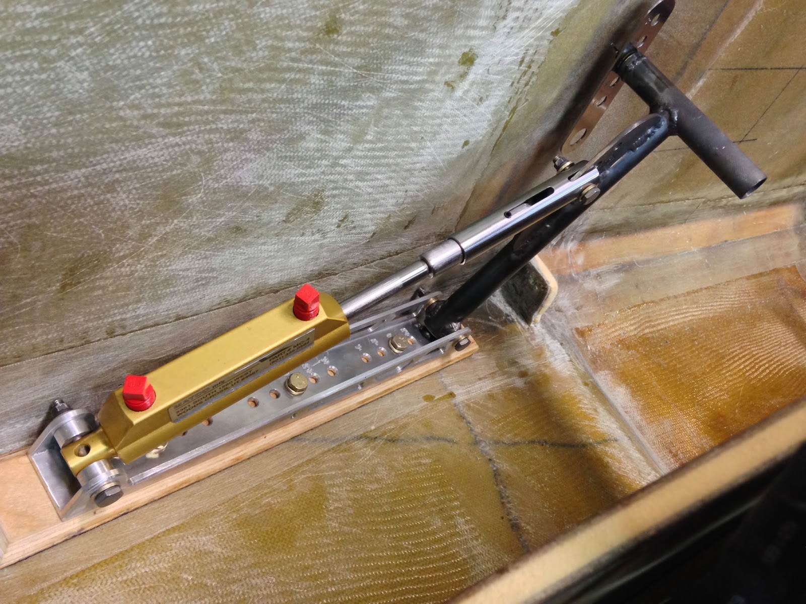
After sitting in the plane for sometime though, it turned out that all of these changes were unnecessary. My left leg rested more naturally against the sidewall, and easily activated the brake pedal along the bracket centerline, this arrangement also eliminated any concerns of side loads being applied to the master cylinder piston. Furthermore, the little stubs felt pretty comfortable to rest the bottom of my heels against, marking the correct foot position for best brake activation. So, I decided to make no further changes, and leave everything as it was.
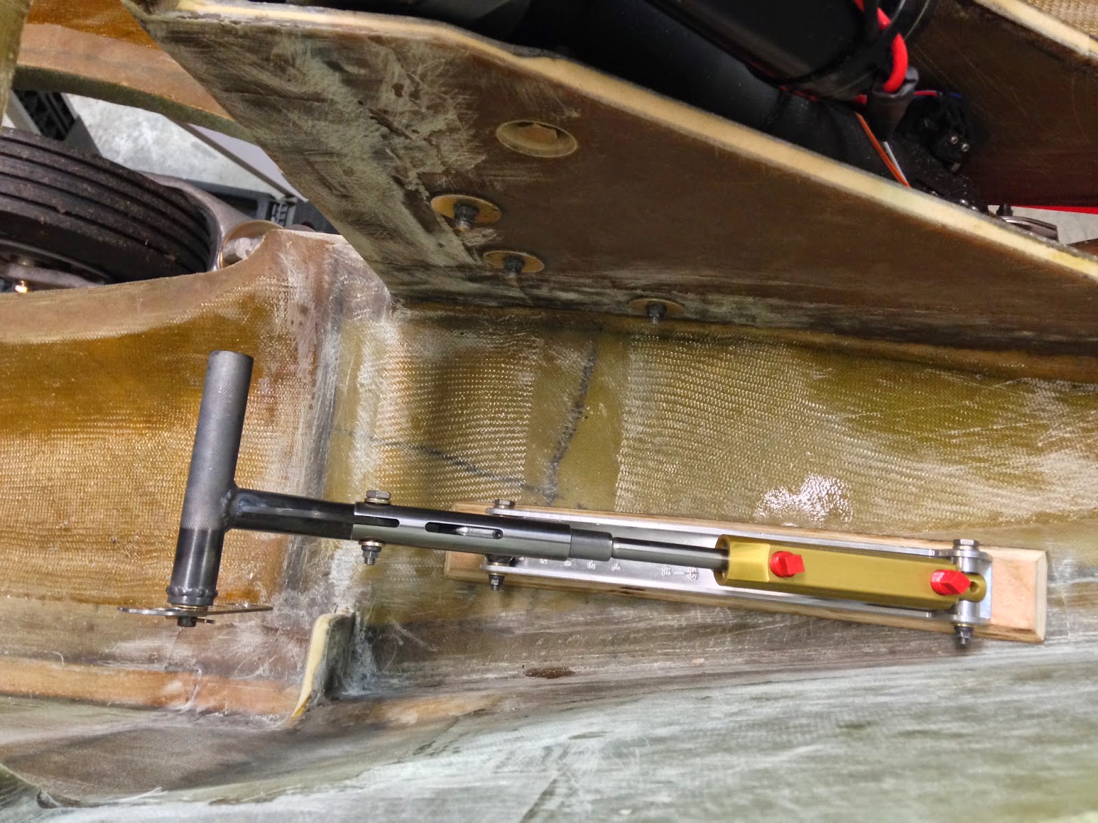
The brackets will bolt to plywood anchors. I am still using the same plywood piece I had purchased for the firewall a few years back.
 |
| Aviation grade plywood leftover from the firewall |
 |
| These will become the anchor points for the brackets |
 |
| A 45˚ chamfer was added to ease laying the fiberglass |
 |
| 3 holes were drilled |
These plywood pieces will be floxed to the nose floor, then fiberglassed over. In order to have good attachment points for the bolts, I followed my friend Ary’s lead, and purchased some Tee nuts inserts for wood from McMaster-Carr.
 |
| Tee Nut |
These worked very well, and were easy to install.
 |
| Tee nuts about to be installed. |
 |
| Tee nuts installed with the help of a small hammer |
 |
| The Tee nuts seem to hold very well |
 |
| I couldn't resist putting the assembly together |
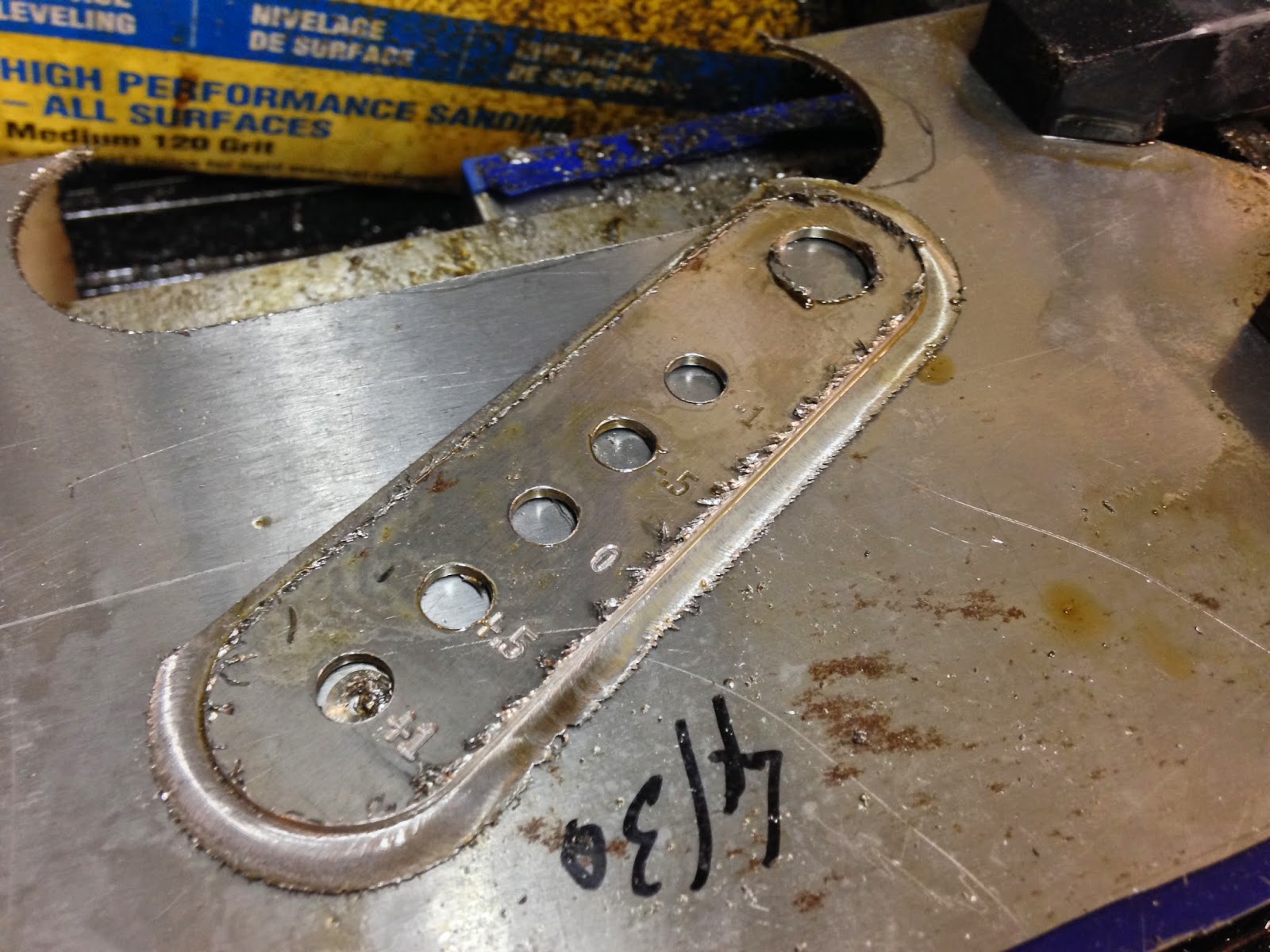
I made two new flanges out of 0.100” (2.5mm) thick 4130 steel on the CNC mill.
 |
| Holes pre-drilled |
 |
| Holes enlarged to final size, and engraving done. |
 |
| Flange getting cut, one 0.007" (0.18mm) slice at a time. |
 |
| The umbilical cord is coming off next |
 |
| Here's the new born all cleaned up |
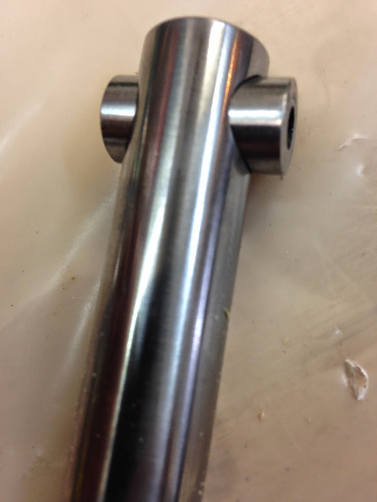
A little lathe work was necessary to create the bullet-like nose of the master cylinder rod extensions.
 |
| Creating the rounded nose that will press on the flange |
 |
| Drilling a hole for the set screw |
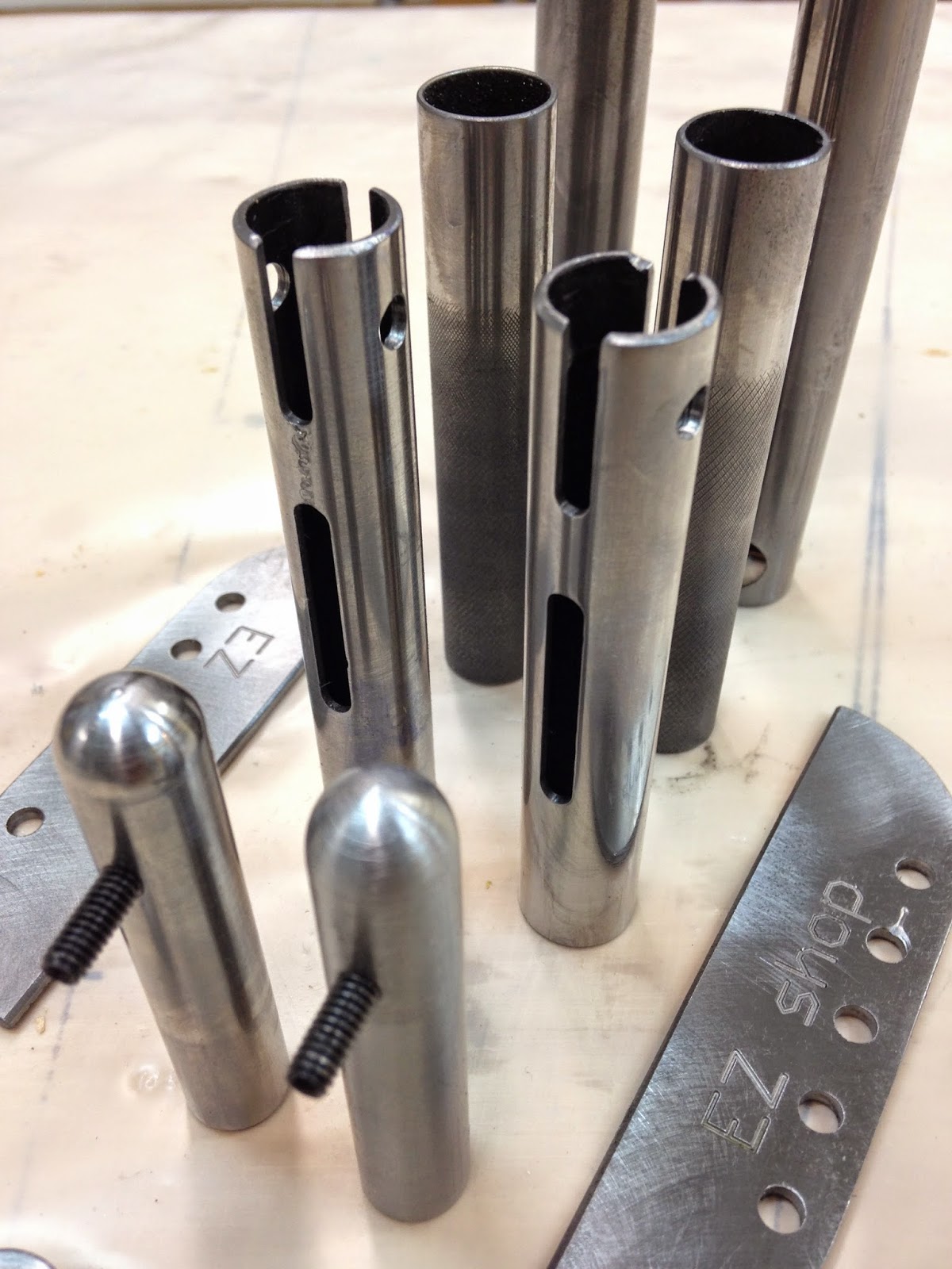
The pedal vertical components were drilled, and cut on the mill.
 |
| While CNC was non strictly necessary here, it helped increase the consistency of the parts. |
The slider piece had its three slots CNC cut as well.
 |
| These were fun to watch getting cut |
 |
| Slider nearly finished, before final cutting. |
Lastly, the rudder cable attachment point was made on the lathe.
 |
| Tapping the rudder cable attachment point for an AN-4 bolt |
 |
| Rudder cable will connect here |
There will be an adjustable piece connecting the top of the brake pedal to the actual rudder cable, but I will design it and machine it when I get back from Europe.
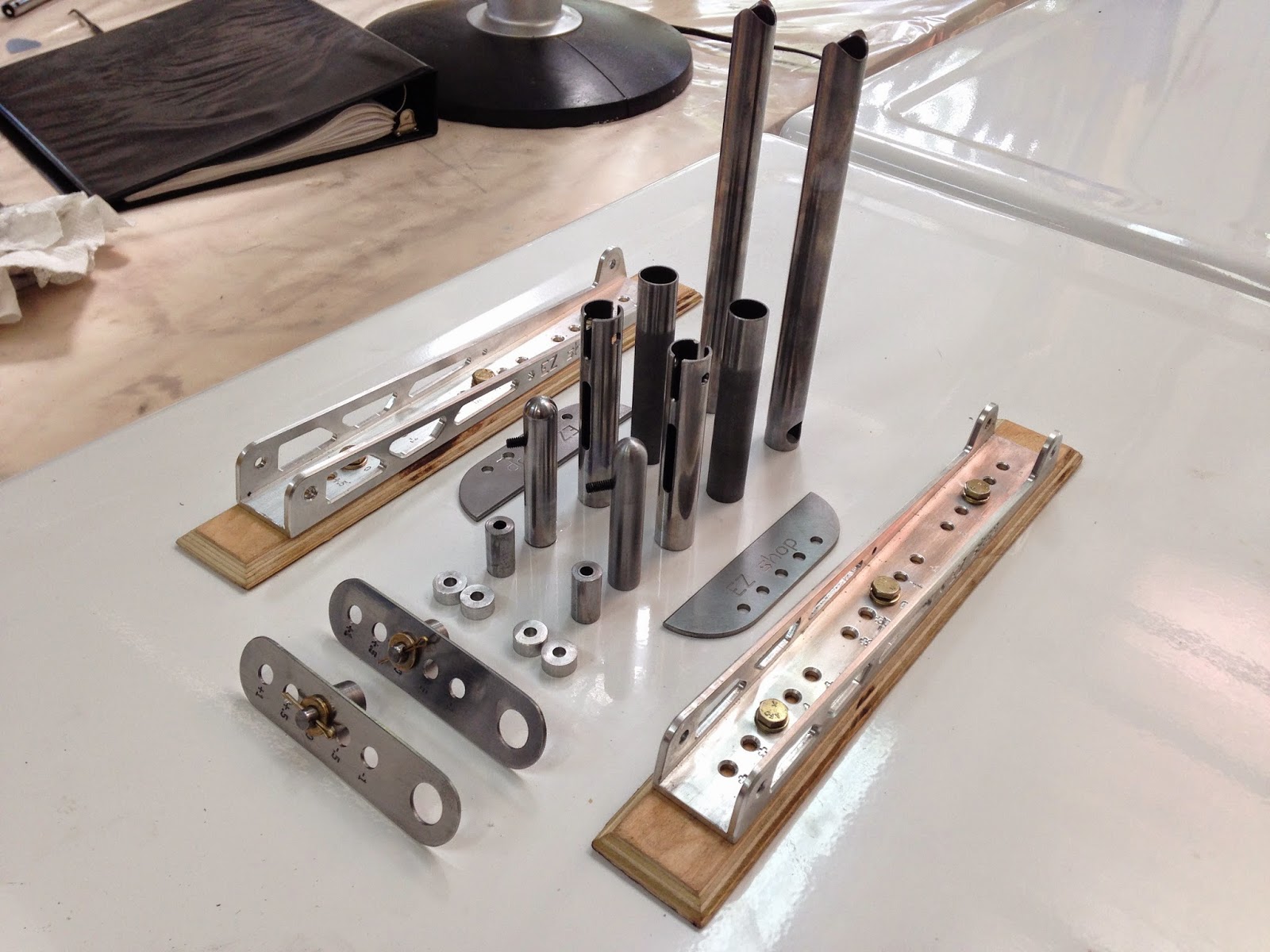
Unfortunately, I ran out of time before I could finish making all the parts, and I had to leave on another trip. So, there will still be a tiny bit of machining to be done next week, before the welding session begins, and I can turn all these parts into actual pedals.
 |
| Almost all the parts for the pedals are finished |
 |
| I'm pretty happy with the quality and consistency of these parts |
 |
| It will take a long welding session to turn all of this into pedals |
One of the issues I had welding 0.100” (2.5mm) thick steel plates to 0.035” (0.89mm) steel tubing, is that the tube melted before the plate was ready to fuse. I was still able to weld them by directing the TIG torch, and the heat, mostly toward the plate. This however was not a great solution, and though successful, the welds turned out very ugly.
What I should have done was to preheat the parts before welding them, and this is exactly what I intend to do next week using a propane torch.


%2Brendered.jpg)