Chronicling my Long EZ construction (and a few other things).
Disclaimer
This blog is for entertainment purposes only, and is not meant to teach you how to build anything. The author is not responsible for any accident, injury, or loss that occurs as a result of reading this blog. Read this blog at your own risk.
In the heat of the moment I forgot that I had enlarged the fuselage, and neglected to enlarge the nose bulkheads... Doh!
I considered increasing the size of the bulkheads, and even remaking them, but after working out the lines over the plans, I realized that the changes to the nose shape were very minimal. Hopefully it will still look svelte.
Because of this, I enlarged only the rear portion of the floor piece...
Modified floor plan dimensions
Duplicating the floor
... then went to work carving the front depression.
Deciding on a cut line
There's nothing subtle about this!
Making the depression symmetric
After mixing up some micro, I attached the foam floor pieces to the nose frame.
Getting ready to glue the foam to the fuselage
Duct tape and wood holding the foam in place while the micro cures
In order to provide a clearer surface for bonding, I elected to remove the bottom NG-8 bolt.
Depression clears the lower NG-8 bolt
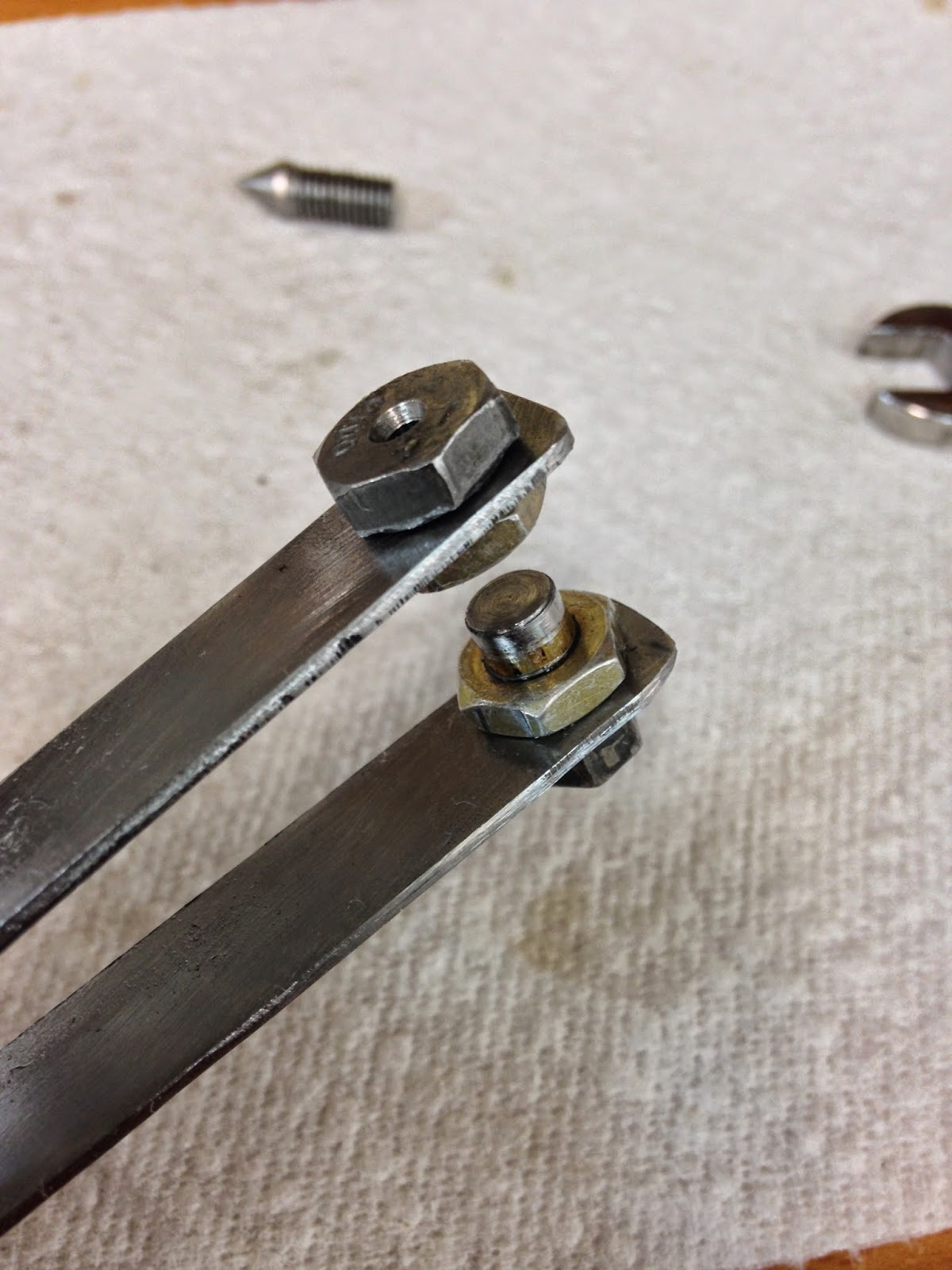
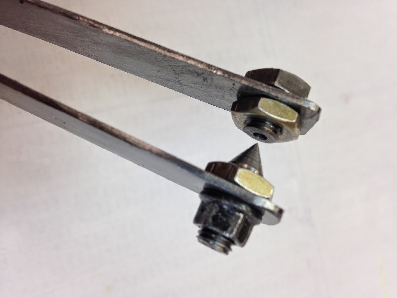
I turned a couple of old bolts down to a point on the lathe, this will help spread out the glass weave as it is being laid over the hole, and prevent epoxy from filling it.
Yes, I did poke myself on accident. More than once.
I did the same for the actuator bracket's bottom bolt.
More blood drawing spikes
A piece of paper served as a pattern for cutting the fiberglass.
Paper template
The foam was prepped with micro-slurry, and a fillet of dry micro softened all corners.
Micro-slurry closing the foam pores
Micro fillet
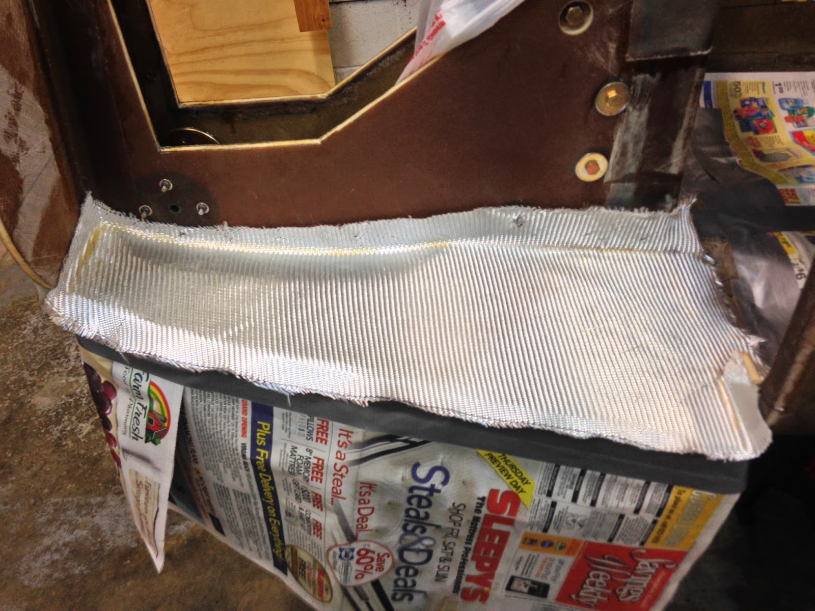
Then it was glassing time.
Fiberglass connecting the floor to NG-30, the front bulkhead, and the fuselage.
Layup complete
Peel-ply added
The next morning I ripped the peel-ply, and sanded the rough edges.
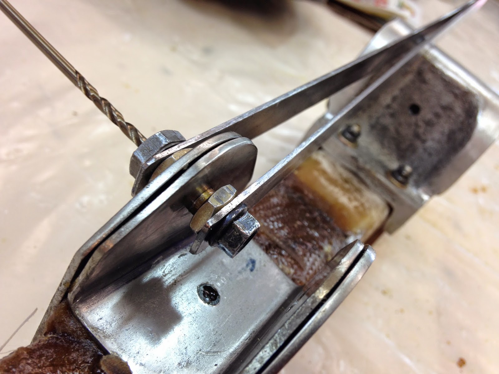
I could spend hours talking about what a pain in the ass it was to drill the holes in NG-3 to match the ones in NG-4, but let's just keep it short.
I wasted a whole day making a “hole duplicator” that not only didn’t help, but actually made things worse, forcing me to become overly creative once again.
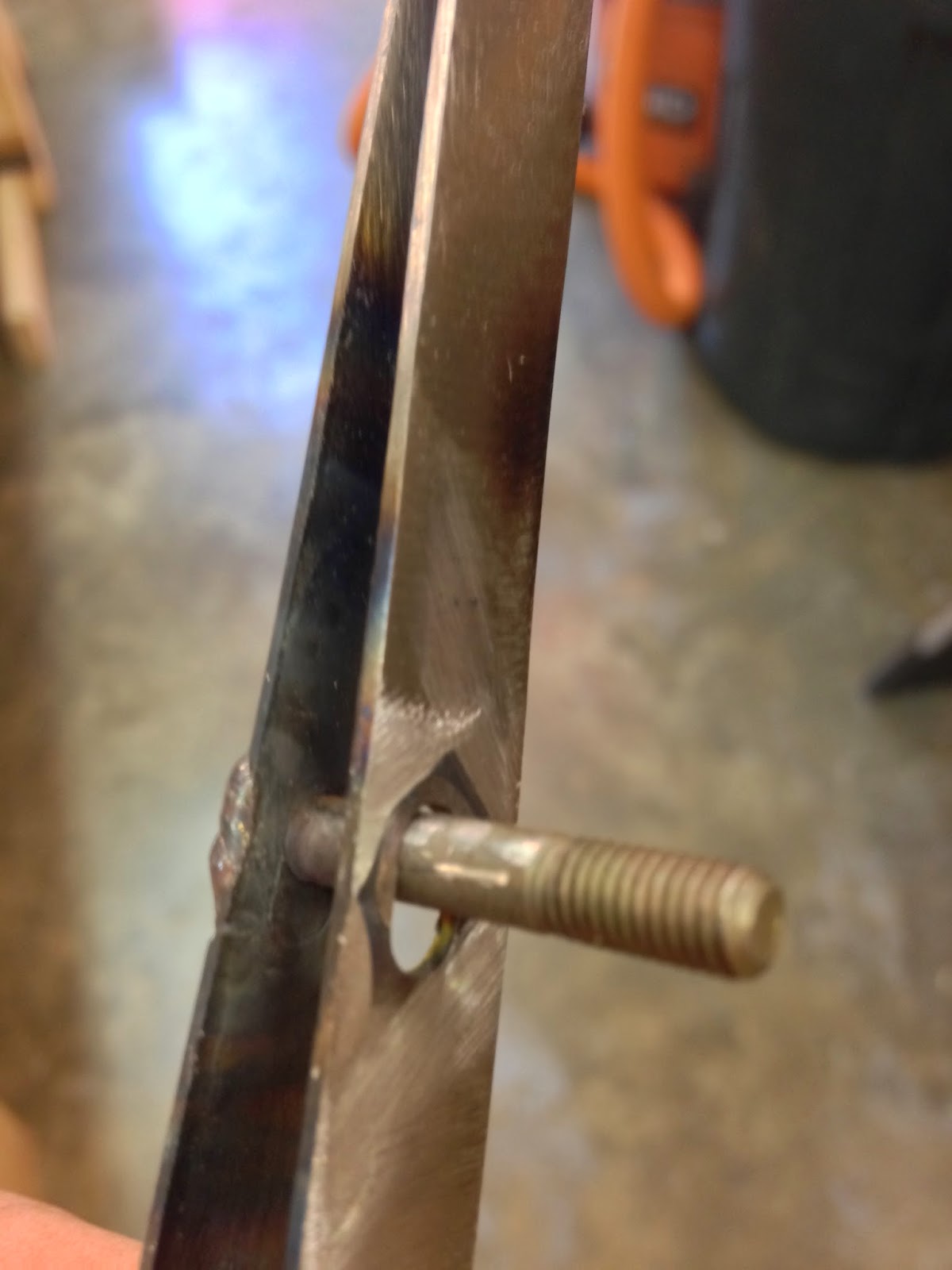
This is the way it should have worked
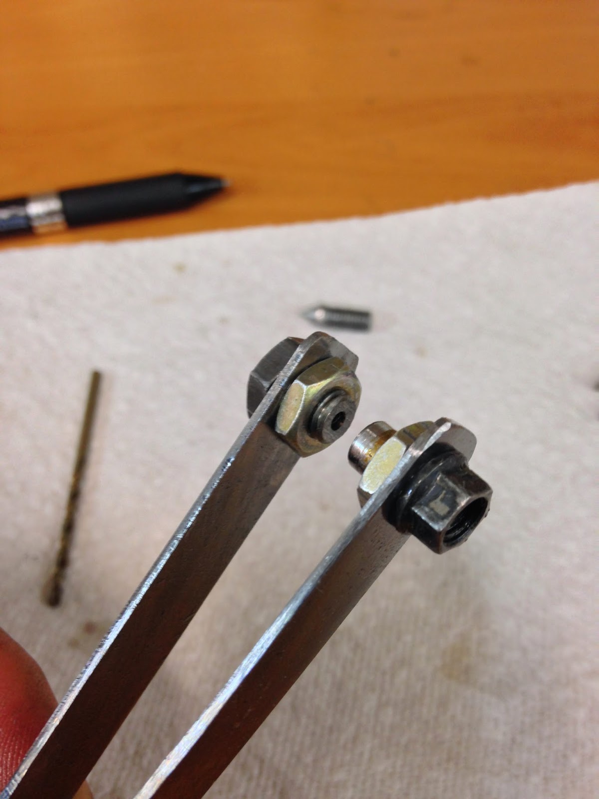
The ¼" stud attachment fit into the hole perfectly
In truth, the duplicator might have worked on softer metal, where the drill bit could have gotten a quick “bite”, unfortunately the hard and slippery nature of stainless steel left the bit wondered about aimlessly, dragging the duplicator with it to all the wrong places.
¼" stud attachment
Hole for starter drill bit
Taper-center attachment (for random size holes)
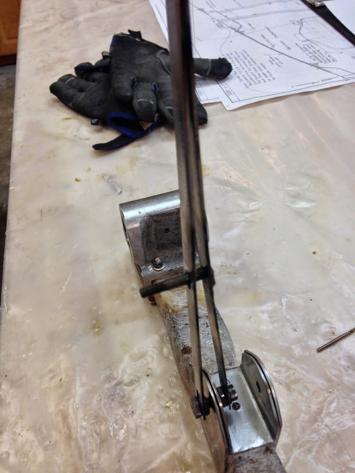
Adding a “stabilizer bar” helped a little, but in the end it just was not up to the task.
Stabilizer bolt to prevent shearing motion
Improved hole duplicator in action
The day's work left me with 4 holes (2 per side)all of which were drilled off center, and a bit unsure how to proceed.
Pissed off, I threw the duplicator in the garbage, but after cooling down, I dumpster-dove to retrieve it, and will probably try it again in the future on aluminum or fiberglass.
Out of desperation, I ended up fitting the complete leg on my mill, and used 1/8” end mill to cut through the outer bracket.
No more "Mr. Nice Guy"!
I centered the mill’s head by eyeballing the situation in a mirror, and making the proper XY corrections.
Checking for approximate concentricity at best
Satisfied that I was as centered as possible with the preexisting hole, I stepped it up to a 3/16th end mill, and finally a 1/4” one.
Enlarging the hole to ¼" (6.4mm)
A 1/4” drill bit was used to reach down to the other side, and mercifully finish the job.
Though that was NOT the best way to do it, in the end the job got done anyway, "So what... who cares!"
I was tired but happy when the gear leg got put back on the nose of the plane for final testing.
Second, and hopefully final gear extension/retraction test.
I did have to move the upper limit microswitch up slightly to reclaim all the additional space I had carved out of F-22, and I also had a slight rubbing issue with one side of the notch in F-22, and that got easily taken care with a little sanding.
Things are good again now, and I’ll be moving on to the nose floor and sides next.
Given the state of drafting technology of the late ‘70s and the complexity of airplane design, it should come as no big surprise when at times there are differences between the plans and reality. These issues would usually get fixed in later editions of the plans, but in the Long EZ’s case there is only edition #1, so you gotta work with what you’ve got.
One such discrepancy seems to have occurred in the nose wheel retraction system department.
One could be excused for assuming that the nose wheel should retract completely into the fuselage, and indeed this seems to have been the designer’s plan.
Designer intentions
However, a little while ago I received an email from my friend Ary complaining that nearly 1/2” (1.5 cm) of his nose wheel stuck out below the fuselage.
Ary's moment of discovery
At first, I thought he might have made some kind of mistake putting things together, but two weeks later, when I temporarily mounted my nose gear, I was shocked to see that my wheel hung about 1/2” below the fuselage as well.
I'm starting to detect a pattern...
Something was amiss, but I just couldn’t put my finger on it. Talking to everyone I know, I discovered that apparently everybody has had this happen to them (casting issue perhaps), but they all chose different ways to address it.
Burt Rutan's own plane
Yep! It's definitely a pattern!
Given that the gear leg follows the outline of the fuselage perfectly, I’ll just assume that this is the way things normally fit in a properly put together Long EZ, and move on to how to deal with it, but that really depends on what you want your nose to look like.
The way I see it, there are three principal ways of approaching this issue:
Leaving it alone, and living with it.
Adding a wedge to the bottom rear of the gear leg in order to correct the casting angle, and tuck the wheel into the fuselage.
Cutting through the floor panel behind F22, and also raising the F22 notch in order to bring the whole leg (nose wheel included) further up into the fuselage.
Every option has its pros, and cons.
Option 1 is the easiest, but it does not really address the issue.
The half door does a pretty good job at covering the protruding wheel
Option 2 requires minimal effort, but it completely addresses the shortcoming. Though there might be some minor nose wheel geometry changes, the spirit of the plans is retained.
This plywood wedge is about to get covered in BID
Option 3 has major impact on many structures which will need to be reworked to retain strength, but it creates enough room to allow the addition of full size nose gear doors, hiding the nose wheel into the fuselage, and creating a perfectly streamlined nose.
Beasley's awesome engineering
Since I’m a sucker for good looking yet difficult things, I will go with the last one, hoping I won’t regret it.
Floor needs to be cut. It will be re-covered later.
Floor BID excised
F-22 notch raised about ¼" (6.4mm)
Surgery completed
Gear leg going roughly ¼" further into the fuselage
Nose wheel barely visible (at an angle)
Nose wheel completely contained in the wheel well (about 0.030" clearance from bottom)
Critical to the nose wheel ability to retract into the wheel well, is the proper geometry of the retraction mechanism. The normal hand operated system comes with precise measurements as to where the NG-3/NG-4 brackets should go, but since I am using a completely different system, these might not work for me.
Plans' directions
In order to make sure the electrical actuator will retract the front gear all the way up, I decided to do a little reverse engineering and the disregard all given measurements. I will test fit NG-3 while NG-1L is in retracted position, and make sure it extends/retracts properly, then I'll have a look at what my measurements turned out to be.
Looking for right NG-3 location
This geometry looked to be working quite well, even though the distance between the hinge point and the bracket bolt hole came up to about 6.15", which is much different from the 6.71" (± 0.05") the plans showed.
Your measurements might vary
I then added one layer of BID and flox.
NG-3 and NG-4 brackets getting floxed
Gear leg cured
Back side
When I get back from my trip, this leg will need a little cleanup, and new holes in NG-4 drilled to match the ones in NG-3.


.JPG)


.JPG)


