Disclaimer

This blog is for entertainment purposes only, and is not meant to teach you how to build anything. The author is not responsible for any accident, injury, or loss that occurs as a result of reading this blog. Read this blog at your own risk.

Monday, December 30, 2013

CNC mill conversion - part 10

Solving more mechanical issues
  
I’ve been meaning to do a lot more work on the landing gear this week, but I’ve been running in “crisis mode” with the mill for the past 5 days. Here’s what happened…


Y motor stalling while "cutting" a circular pocket


Now, what you are seeing is the Y motor stalling and loosing steps. Not good!!! This was with the mill running at the full speed of 120 in/min (5 cm/sec). The normal cutting speed would be more around 20 in/min (1 cm/sec) depending on depth of cut, material, coolant, etc.

So, I spent a lot of time on the Mach3 forums (mill controller software), only to find out that while the backlash compensation (software feature) I was using actually does a few good things, it also sometimes creates new problems. In other words, they discourage you from using it, and mostly suggest that you to spend more money eliminating backlash by using expensive ballscrews, ballnuts, etc. 

Of course!

Slowing down the feed, I was able to run the mill just fine at 50 in/min (2.5 cm/sec), but there was one other thing that bugged the hell out of me… while the X axis was smooth as butter, the Y axis squealed like a pig going to the slaughter house! 

I adjusted the gibs, the ballscrew attachment to the table, the attachment to the motor, and to the base at least 50 times, with little success, since the squeal never really went away, it just migrated to different sections of the travel. 


An example of gibs


It seemed like the table was being dragged a little crooked by the ballscrew, generating a lot of friction and noise against the sides of the slot that contained it. To make a very long story short, I eventually noticed that the unrestrained ballscrew whipped about a lot when the motor turned it, which meant that either the screw was bent, my machining of it was off, or there was too much offset between the motor’s shaft and the ballscrew.

I decided that my couplings were probably too rigid, so I ordered some flexible ones. 

The Chinese Quality Control crew must have been asleep that day, since the motor’s shafts turned out to be 0.002” oversize, and the coupling would not fit, so I had to turn the motor’s shafts down in the lathe. Luckily I had purchased motors with a through shaft, and I was able to accomplish the task, albeit having to resort to some pretty creative machining.


Try figuring this out!


After putting everything back in its place, I gave it another shot.


Flexible coupling


Unfortunately, all of that work did not solve the issue! Obviously this was not the cause of my problem, and it “only" cost me $80 in parts to find out. 

Looking at the Y ballscrew, it seemed pretty straight, but when I tested it it was way off. I’m not really sure what happened there, but I must have botched it, since it ended up not being concentric.


Ballscrew 0.009" out of round 


Trying to save the ballscrew, I decided to touch up the machined part slightly on the lathe. Needless to say, that part of the screw needs to be very precise, as it is held in a spacer block with 4 bushings and 2 ball bearing races.


Ballscrew captured in the spacer block


Although I was very careful, the tolerances were just too tight, and I ended up turning it down a bit too much. 

The ballscrew was now wobbling within the spacer block as well, in addition to the squealing, and a huge 0.020” backlash. By this time I was pretty dejected with the whole CNC idea, and felt I had bitten a lot more than I could chew, swallow, or digest.

I decided to go for broke, sacrifice the Z axis ballscrew to make a new Y axis one. This would mean grinding all over again, which I never wanted to do again due to the abrasive dust going everywhere, causing visible wear, and necessitating a complete lathe teardown and clean up in the past.

This time though, I took a lot more precautions against the dust, covering everything I could with adhesive tape, cloth, and aluminum foil, and then started grinding.


Grinding wheel and ballscrew particles combining to form a hard mound


The next day, I threaded the ballscrew, and pushed it into service… Oh, the sweet sound of silence! 

Success at last! The pig had been finally killed, and all squealing stopped.

Happy as I was about the sound NOT coming from the table moving up and down the Y axis, I still had the awful backlash to deal with, at least 3 to 4 times the amount present in the X axis, which made any precision work impossible.

After testing, adjusting, taking apart, lubing, and putting together the Y axis components for the next 2 days, I was still no closer to a fix than I had been all along, when finally a lightbulb went off inside my head, and a new theory emerged.

What if the theoretical 10’000 micro-steps the motor had to make for the ballnut to travel 1 inch (and that I had programmed into Mach3), were not as accurate as the motor specifications suggested? So, I placed Mach3 in “learning mode”, commanded a 3’ travel, and got the usual 2.980”. I entered this value into Mach3 which replied that the new steps for 1’ would be set to 10’045.24826. I just accepted that.

The next time, I asked for a 3 inch travel, and I got 2.9995". Much better now, and... it was repeatable :-)

So I did the same thing for the X axis. The steps got set to 10’009.69097, and I got 8.999” for a 9” travel command :-)

Now, looking at the specifications of my DROs (digital read outs) they are only within ±0.0015” accuracy over 12” of travel, so I just cannot measure that level of precision with what I’ve got. For that I would need glass-scale DROs whose cost would be much greater than that of my mill.

Very happy with my new measurements, I ran the 2” circular pocket test again last night at full speed (120 in/min) without backlash compensation, and here’s what I got...


Not perfect yet, but nearly there.


I am very happy with these results for now, but it should get even better ones as I reduce the backlash even more.

My backlash turned out to be 0.004” in X, and 0.005” in Y, which is not bad for cheap $30 Roton ballscrews, and in line with their online claim. I will order some oversize ball bearings this week, in an attempt to try driving those values down even further. This means that I will forego the Mach3 backlash compensation with all its drawbacks, and just mill away happily ever after as soon as I replace the ballnut bearings. 


Backlash measurements


Monday, December 16, 2013

Main landing gear - part 9

Wheel, brake, tire and tube (5.7 hrs)

With the left gear leg cured, and the new MATCO brake shoe in hand, it was time to finish this side.


Additional 3+3 BID plies cured


It took a lot of work just getting the bolts off, but when they went I had a much better shot at trimming and sanding the fiberglass.


A little trimming is in order


After a lengthy sanding session, I made two templates of the brake shoe attachment bracket, and used the sharpened bolts to help me locate them on either side of the leg bottom.


Leg trimmed, and brake pattern being located

Mirror image opposite side

Template in place to aid in trimming the leg end

One last check before the irreversible cutting took place


Then I started cutting and sanding. This was painful on an emotional level (as usual), but also on a physical level this time, since the gear bow is a very tough structure, and cutting/sanding it is not an easy task.

Needless to say, a mistake at this point would have been critical, as the part would likely have become an expansive boat anchor. So, tension was running high until the very end, and progress was slow due in part to the difficulty of the task, and in part to a conscious effort made to avoid cutting too much off at one time.


"Here we go..."


I had to go back and forth countless times in a nearly endless cycle of sanding, mounting the axle, marking areas to be sanded again, removing the axle, and repeat...


Trimming and sanding in increments

Here you can see where a little more sanding was necessary


But eventually I got to the point where the fit was good and the brake housing no longer touched the fiberglass leg, and I snugged all the hardware.


Caliper in their final position

These 6 bolts, and the outer brake pad, need to be removed before the disk brake can get in there.


The only thing left to do was getting tire, tube, and wheel to play nice with each other long enough to put them all together for good. This was not too hard, but it certainly required a methodical approach.

First I sprinkled some baby powder inside the tire, and anywhere rubber touched aluminum. I also put a lot of it, maybe too much, on the tube itself, to help it slide a bit better. I slightly inflated the tube, and slid it in the tire.

The red dot on the tire marks the position of the tube’s inflation valve, to help keep the tire more balanced. Marks on the wheel also require alignment with the red dot.


Valve stem in correspondence of the red dot

Baby powder is used to help things slide in their proper places


One of the issues I ran into was that as soon as I put the tire on its back, the three main bolts would fall out the back of the wheel half, making it impossible to get to them from the top. I found a roll of tape that was just the right size, and used it to rest wheel and bolts on, while I pressed hard on the top half of the wheel and tire trying to close the deal.


Perfect spacer

This will hold the bolts up as I rest the wheel upside down

Now, a little pressure will let the bolt heads through just enough to get washers and nuts on them.


The tire makes for a pretty good spring while trying to squeeze the two wheel halves together, furthermore it is imperative that the tube does not get pinched in between them, or it’s game over. I found this last part to be easier than expected, and the tube was cooperative for the most part.

Mounting the wheel on the gear leg turned out to be an exercise in weirdness though. 

Since the brake pads are mounted on the inside of the rim, first I had to separate the disk brake from the wheel, then I had to remove the 6 bolts that hold the brake pads together, next I removed the outer pad, put the disk brake onto the axle like a freesbe that had been thrown up there, then I reinstalled the outer brake pad with the 6 bolts making sure the disk brake was between the pads. At this point I mounted the wheel on the axle, snugging it down with the main axle bolt, and rotated the wheel until the disk brake lined up with the matching holes in the wheel, then bolted it down.

Removal is the reversal of the assembly.

I sure hope I won’t have to change the brake pads too often!


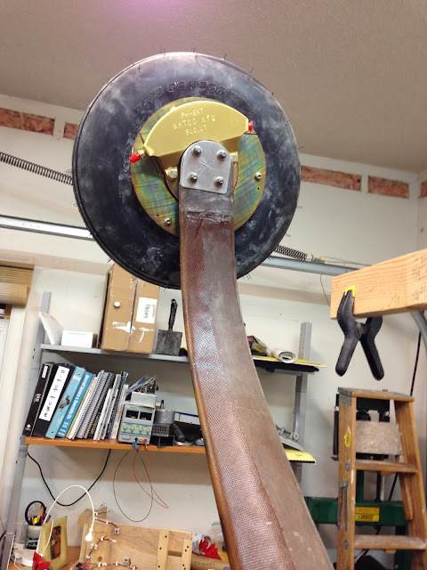
This wheel/brake/tire combo looks awesome!

The caliper grasps the disk brake from the inside rather than the outside

Grass strips here I come (carefully)!

Right side to go


“Tooling up” - Sanding implements

Perma-Grit hand tools

I wanted to take a moment to share with you a new set of tools I have just purchased from Aircraft Spruce (item 12-00056), and that have already proven themselves to be a quantum leap better than anything else I have been using up to this point, except perhaps my huge home made sanding block.

The coarse Perma-Grit sanding system


In retrospect, I should have paid more attention when my friend Wade (LongEZpush.com) told me these were the best sanding tool he had ever owned. It’s just that, when he mentioned the price ($75), my brain went into an automatic memory dump/clear all cache mode, and I relegated them past the “nice to have” category, well into the luxury category.

The item description mentions that: “Perma-Grit Tools are made of Tungsten Carbide Grit, one of the hardest elements available, second only to diamonds. They are specifically designed and developed for aircraft builders, woodworkers, and modelers. These tools will cut, sand and shape tough composite materials, saving homebuilders hours of building time. Ideal for fuselage shaping and wing building, these tools are highly recommended by several kitplane manufacturers. Available in coarse (180) & fine (320) grit”.

I did get the coarse type, and so far I have used them to file down the landing gear bow. That meant sanding through a few inches thickness of coarse fiberglass, and I have to say I am impressed at how quickly they ate through it, and how durable they are.


If you have the need, and the means, definitely add them to your Christmas shopping list.


Friday, December 13, 2013

CNC for dummies

Video series 
  
Against my better judgement, I decided to videotape a small series on what it took to get the CNC mill cutting correctly in the XY plane. 

I have to admit that I suck at making videos, so "you get what you paid for". Still, I hope you might find something interesting, or even useful contained herein.

This series is not meant to be a tutorial on how to build and troubleshoot a CNC machine, rather it is an account of the challenging, and rewarding journey I embarked on, when I decided to bring this complicated piece of equipment to life.

A few end-mills have been harmed in the making of these videos, parental discretion is advised.


WARNING

Do not view these videos while driving or operating heavy equipment as they might induce mental confusion and/or sleep. A few instances of sudden boredom have been reported.


The endless rant


The software


One last test before cutting


An unexpected issue derails my plan


A big problem threatens the viability of the CNC concept


Recovering from disaster


The elusive taste of success, at last!


So, here's the finished bracket...


Friday, December 06, 2013

Main landing gear - part 8

Left leg toe-in final adjustment (3.0 hrs)
  
Drilling the axle holes through the left leg left me with a small dilemma... how to get the 4 bolts through the 6 layers of wet fiberglass I would need to add, without making a complete mess.

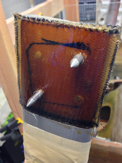
I decided to sharpen the same bolts I had cut (then recycled) when I worked on the landing brake hinge. I hoped I could use them to part the fiberglass neatly, thus avoiding unraveling the sticky mess.


After, during, and before.

Test fit


I ran a quick “proof of concept” test on a few layers of dry fiberglass scraps.


Splitting fibers


In light of that resounding success, I decided to move on to “full scale implementation”, but first I glued the aluminum square back on the axle.


Hot glueing


With the axle ready for action, I cut 6 plies of BID, and pre-pregged them into 2 “patches”.


6 plies of BID

Pre-preg patches ready for deployment


I applied one patch to one side of the leg, then speared it from the opposite side with the bolts, in order to separate the fibers. I had to apply some pressure from the fiberglass side because it tended to lift up, but it eventually settled back down nicely.


Wet fiber splitting in action


With the 4 holes parted on one side, I applied the other patch to the opposite side. Next, I ran the sharpened bolts back through the same holes, but in the opposite direction, repeating the fiber-separating procedure on the new patch.


Splitting fibers on the opposite side


The sharpened bolt method worked out perfectly at separating the weave, dry and wet as you can see, and will be relied upon again in the future. The only thing to watch out for is when retracting the bolts, the tendency on the wet cloth is to pull a few fibers back through the hole to the other side. Not a problem really, just a minor annoyance.

With four clear paths through the gear leg, I installed the axle with temporary bolts.


Bolts made it easily through the wet mess


Then, I installed the backing plate, cleaned up the threads with Acetone, and added a bunch of temporary washers and nuts.

Far from being over, the work was actually just beginning, as the delicate process of incrementally tightening the bolts, and repeatedly checking the toe-in got underway.

I was trying to achieve between 0.1” to 0.2ish” (2 to 6 mm) difference in measurement between centerline-to-axle, and centerline-to-aluminum-square distance.


I was very happy to see a little over 0.1” difference at the 21" mark, and let the setup cure overnight (I could not measure at the 24" mark due to the wooden structure I had erected).


B/2 distance in inches

A/2 distance in inches

Curing overnight


All it’s needed now is some minor sanding, and a little trim where the brake caliper will go. 

I’ll do that next time, but while I’m on the subject of brakes, I thought I’d share what I found when I looked a little closer at the brake pads...


Cracked brake pad

Close up


Yep! There is a crack right through the rivet! And no, they have not been dropped!

The guys at MATCO were very nice about it, and offered to replace the pad at no cost, which I’ll do soon. 

Kudos to MATCO!