A faster and more reliable drive
I know it's probably not the most exciting of topics, but there's got to be at least one person out there who finds this interesting.
So, in the spirit of documenting all I've done, this post is for you, and you know who you are!
Still reading? See, I told you!
Back on track... I had been tinkering with the belt drive conversion idea for sometime, and while I appreciated its advantages, I did not think it was strictly necessary for me at this time.
There were however those few improvements I was looking forward to:
- much quieter operation
- increased reliability by bypassing all plastic (yes, plastic) gears used inside the mill’s head
- more than doubling of the high speed to 4300 rpm, compared the original 2000 rpm
I had seen a few before and after comparisons of noise levels online however, and I was not convinced.
For one thing, the maximum amount of noise picked up by the microphone depends on the microphone itself, its proximity to the source, what it is attached to, the software running it, and how the gains are set up. Once the sound hits the "red zone", it doesn't matter how much louder things get, the sound just gets cut off.
So, because a sound is pretty loud on video doesn't mean that it is representative of the actual sound level. Indeed, most videos of this kind make it a point to highlight the fact that the belt drive is actually much quieter than it appears to be, and the gears are much louder then they sound on video.
Ultimately this point has to be taken on faith, unless one has seen a live before and after demonstration.
As far as the reliability issue is concerned, I had not had any problems with the mill (yet), although I did crack a plastic 80 tooth gear on the lathe, so I'm familiar with how fragile they can be.
It is common knowledge among users of these kind of machines, that it is not a matter of if, but a matter of when the plastic head gears will break, so most people are quietly dreading the day when it will happen to them.
 |
| Mill's head taken apart revealing the drive train |
To minimize this possibility, I have gotten accustomed to taking multiple light passes with my cutting implements. This does increase the time spent machining a part, and should improve the gear’s lifespan, but one can never know for sure.
The problem is not so much that replacement gears might be expensive, but that they require special pullers to take them out, and put them back in. There is also no place I know where one can buy them anymore, so they need to be manufactured at home before the mill (or lathe since they use the same gears) is down for maintenance.
The belt drive is such an improvement in this respect, because it has the ability to slip when overloaded, and replaced when needed without tools.
I didn’t find the speed increase argument compelling at the time, but it was something I wanted so that I could engrave parts in the future, like instrument panels, circuit boards, etc.
What precipitated my purchase, was the sudden availability of the kit online, and since this kit is constantly out of stock, I pounced on it.
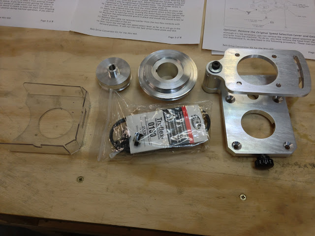 |
| What's in the box |
Installation was simple, with the only issue being the hole for the spindle locking bar being a bit too tight. I just chucked the bar to the lathe, and turn the business hand down a few thousands. Easy!
The mill now is unbelievably quieter, no screeching plastic noises, just smoothness both in low and high gear.
I am very glad I did the conversion now.
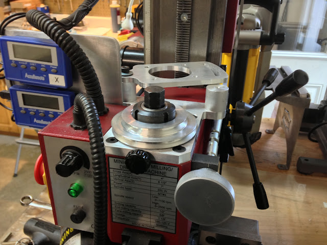 |
| New pulley and bracket in place |
 |
| DC motor running a new pulley in lieu of the old gear |
 |
| The new high gear selected |
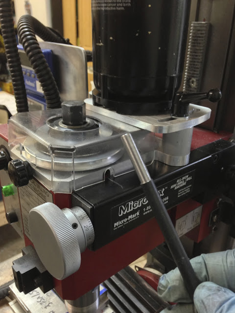
 |
| Installation completed |
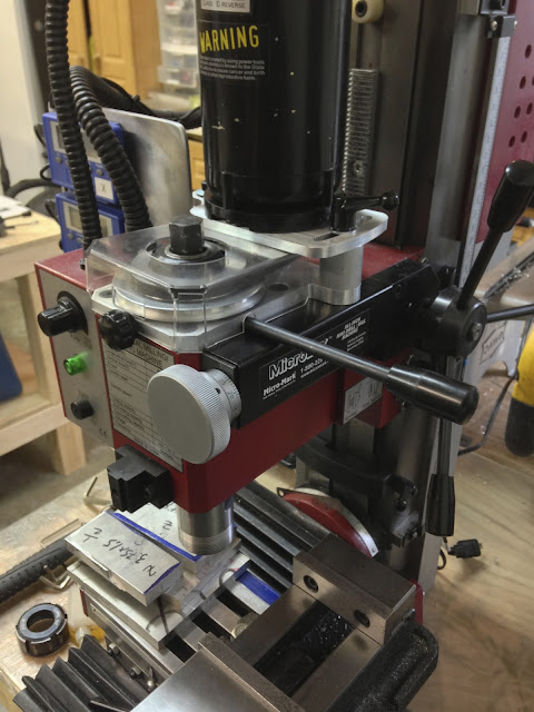 |
| Spindle lock bar in position (used to change cutting implements) |
 |
| End of spindle tool turned down on the lathe for better fit |
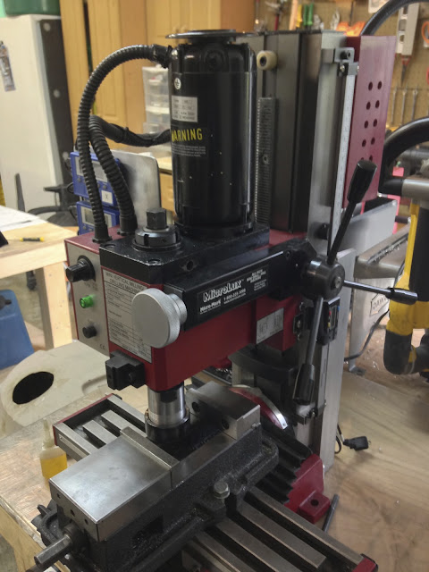 |
| Before photo... |
 |
| ... and after. |
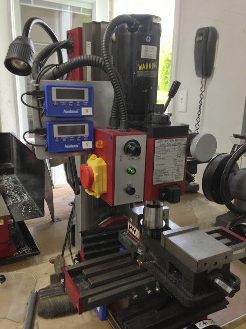 |
| Another before... |
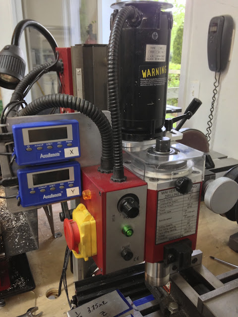 |
| ...and after. |
By the way, this mod is perfectly compatible with a possible future CNC conversion ;-)


