Disclaimer

This blog is for entertainment purposes only, and is not meant to teach you how to build anything. The author is not responsible for any accident, injury, or loss that occurs as a result of reading this blog. Read this blog at your own risk.

Monday, December 24, 2012

Ch. 8 - Seat belts


Creating and installing the hard points (15.0 hrs)  

This is one of those instances where I purposely got slightly out sequence from the plans.

The original progression calls for glassing the outer skin of the fuselage first, then install the seat belts hardware. Regrettably, this forces you to cut 8 holes into your newly skinned airplane.

My friend Wade had the insight of switching things around, and installing the hardware before final skinning. This allowed him to achieve a smooth surface free from of holes.

Being one not to let a good idea go to waste, I decided to reuse it on my own build.

As usual, all I had to go on were two drawings from which to fashion wood and aluminum parts.


2024-T3 Aluminum Angle 

Cutting the individual tabs

Seat belt attach points to be

Reaming one of the holes

Reproducing the chosen shape

Mostly finished tabs


Just as I did with the main landing gear brackets, I used Alodine to help protect the parts from premature corrosion. This is some really toxic stuff, and it’s better used outside.


Alodining setup

Aluminum etching in action

Alodining the seatbelt attachment

Air drying

Tabs ready for mounting


Before I could attach them, the airplane structure needed to be beefed up with additional plywood inserts, and 7 layers of BID.


Plywood reinforcement

All parts ready for floxing

Flox applied to the back of the plywood

Plywood in place

BID getting readied

7 layers of BID

BID in place before  peel-ply

Peel-ply in place


At this point I let the fuselage cure overnight. The next day I removed the peel ply, drilled the holes for the bolts, and countersunk them on the outside. 


Pee-ply removed

The most difficult hole to drill - the first

Using the carpenter square to aim the drill bit

Counter-boring the outer side

Bolts inserted from the outside


The final step was to flox the aluminum tabs, and torque the bolts.


Floxing the tabs

Tab in place with nuts torqued to 60 in/lb

Same thing after clean up

Front seat with seatbelt tabs in place

Rear seat with seatbelt attachment tabs


Thursday, December 20, 2012

Ch. 7 - Fuselage exterior - Part 4


Trimming the top longeron (1.0 hr)  

Looking back at it now it makes perfect sense, but the all knowledgable hindsight would require some more time before making its presence felt.

And so it is, that my balding spot received 24 more hours of vigorous scratching, thanks in part to some slightly ambiguous drawings.

I shall recap my confusing journey for the benefit of future travelers, so that they might not be bogged down by such pesky details.

It all started with the drawings on page 7-1, section A-A in particular...   


Page 7-1


... and a suspicious warning in CP#27 (LPC #50) not to follow such path, but to rely instead on a different chart, the life size A-2...


1:1 scale A-2 drawing


... regrettably, the more I stared at it, the less sense it made. For one thing, it was a very different view altogether, and then there was no indication whatsoever of what had changed. 

Struggling to extract a 3D image out of the 2D drawing of the fuselage side view, I eventually understood the issue, but obviously not its magnitude, thus missing out on the one all important detail that eventually became the focus of my mad search for truth.

The only obvious thing to me at the time, was that shaving the longeron should begin 6.5” (16.5 cm) from the front of F-28.


Making sense of the drawing

Outlining the course of action


The first alarm bells started going off right as I sketched the proposed trim line, but hear them I did not, captivated as I was by the strange looking intersection between the longeron and F-28. 

Strike one!


Hmm... something's up!


While a psychologist would certainly have a fancier name for it, I will just describe my thought process as denial, and rationalization. For one thing, it was only off by a quarter inch, and then, it was probably due to my F-28 modifications anyway. 

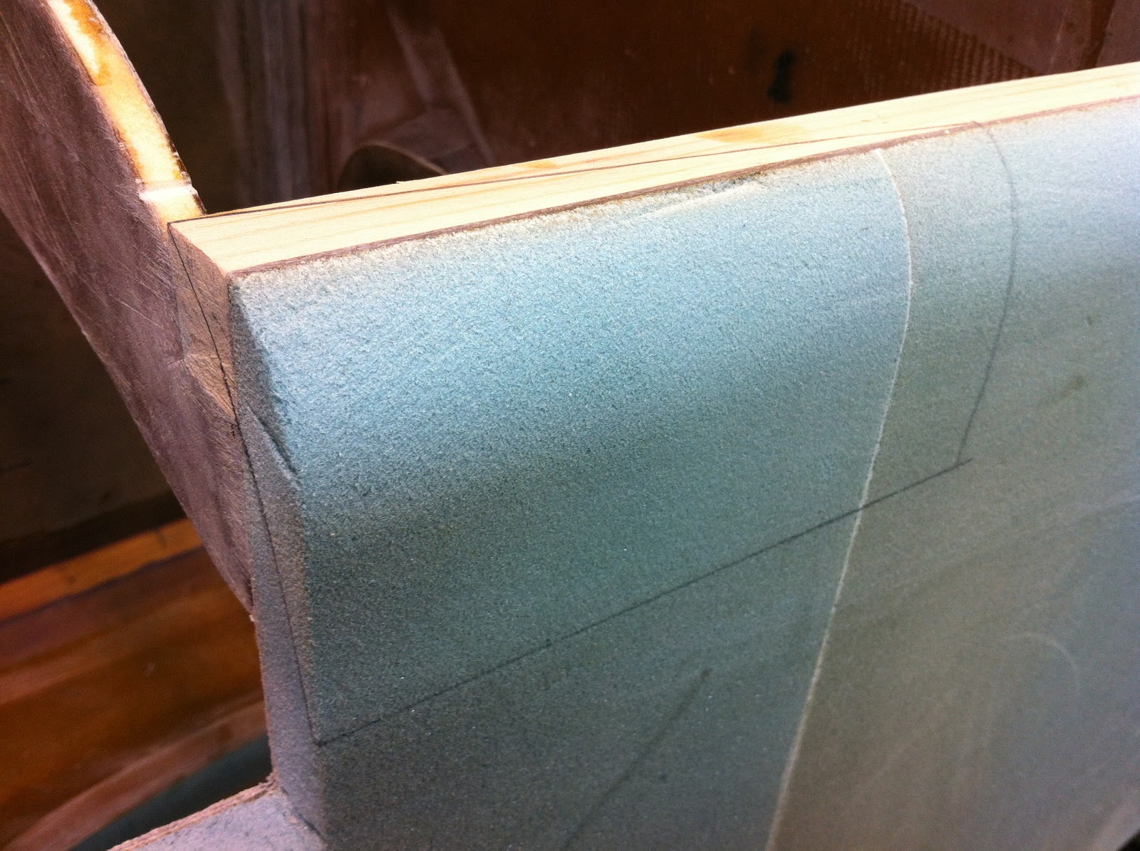
With the argument over whose fault it was won, I set off to the manual task of sanding wood and foam. Unbelievably, the final result resembled exactly what I set out to achieve, but by this time I had grown unhappy with the unsightly notch my work had left on top of the plane.


Hideous notch in plain view


I could have easily blended sidewall, longeron, and F-28 seamlessly, but only by further reducing the longeron cross section...


Post-it note brainstorming


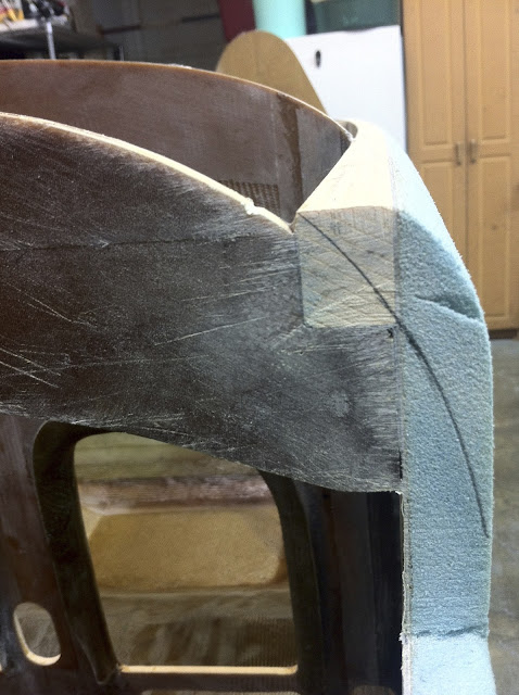
... and forcing a dip in the top of the longeron that was definitely not in the plans. 

A quick poll of my friends yielded no easy breakthrough, with opinions ranging from “I don’t know”, to “it doesn’t really matter”. Growing increasingly frustrated, I resorted to searching through my photo archive, to check out what other builders had done about it in the past.

Wouldn’t you believe it that my good friend Walter’s fuselage sported the odd dip? 

Alarm bells going off again! 

Huh?

Forward longeron sanded to dip

Beautifully straight top of longeron


Poor thing! Surely he must have gotten confused as well, and made the same mistake I was trying so hard to avoid!

Strike two!

So, there I was, with a beautifully shaped fuselage that strangely did not fit.

Luckily for me, a series of emails that forced me to explain multiple times to others, and to myself, where the trouble lay, eventually helped turn the tide of insanity that nearly drowned me.

Saved from striking out, I finally realized that a dip was exactly what the drawing A-2 was calling for all along, had I just "listened" to it more intently. 


So that's what that was!


The new section A-A looked more like this...


Finally getting the point


Nothing left to do but grab the sanding block, and get back to work.


Newly contoured, and sporting the dip!

Highlighting the longeron dip

Right side is dipping as well

Eagle-eye Walter was right once again!


Tuesday, December 18, 2012

Ch. 7 - Fuselage exterior - Part 3


Trimming the fuselage top (3.5 hrs)  


The next task was trimming the top edge.


Fuselage edge to be worked on


The biggest issue here was mostly a psychological one, because I needed to cut off a part that I worked so long and hard putting together. 


Inner and outer measurements


As the old adage goes “measure twice - cut once”, I spent a good 30 minutes looking at this cut from every possible angle, then finally just went for it.


No going back now

Off you go...

I sure hope I don't have to put this back on


I cut it slightly high, than sanded it down to the drawn pencil line.


Sanding things down to the proper size

Finished edge

Interesting cross-section (up is forward)


With the psychological barrier shattered, it was much less painful to cut the right side.


Here we go again...

... and again.


I decided to refrain from cutting the round elevator tube hole for now, because I will be using the offset tube that the Cozy girls manufacture, and it is possible that it might require a slightly different size hole.

Like the fuselage bottom, the top required quite a bit of sanding to bring it down to match my wooden template's shape. This time it didn’t take nearly as long though, as there was a lot less to cut away, and it was purely foam.


Right side initial filing

Opposite view

Contour template in action

Finished right side

Checking the profile with a contour gauge


Left side done

Broader view

Tonight's work