Disclaimer

This blog is for entertainment purposes only, and is not meant to teach you how to build anything. The author is not responsible for any accident, injury, or loss that occurs as a result of reading this blog. Read this blog at your own risk.

Friday, June 29, 2012

Ch. 5 - Fuselage sides LH - Part 3


Rear longeron (2.5 hrs)

The list of things to do this morning was pretty short. Number one on it was finishing the lower longeron by adding a triangular stringer.
First thing to do was removing the nails, which was accomplished in a very traditional manner, twist and pull.


Then I got sidetracked admiring the sidewall, and decided to go for a “glamour shot”. I figured it would be good for showing how all the bulkheads will eventually fit together.


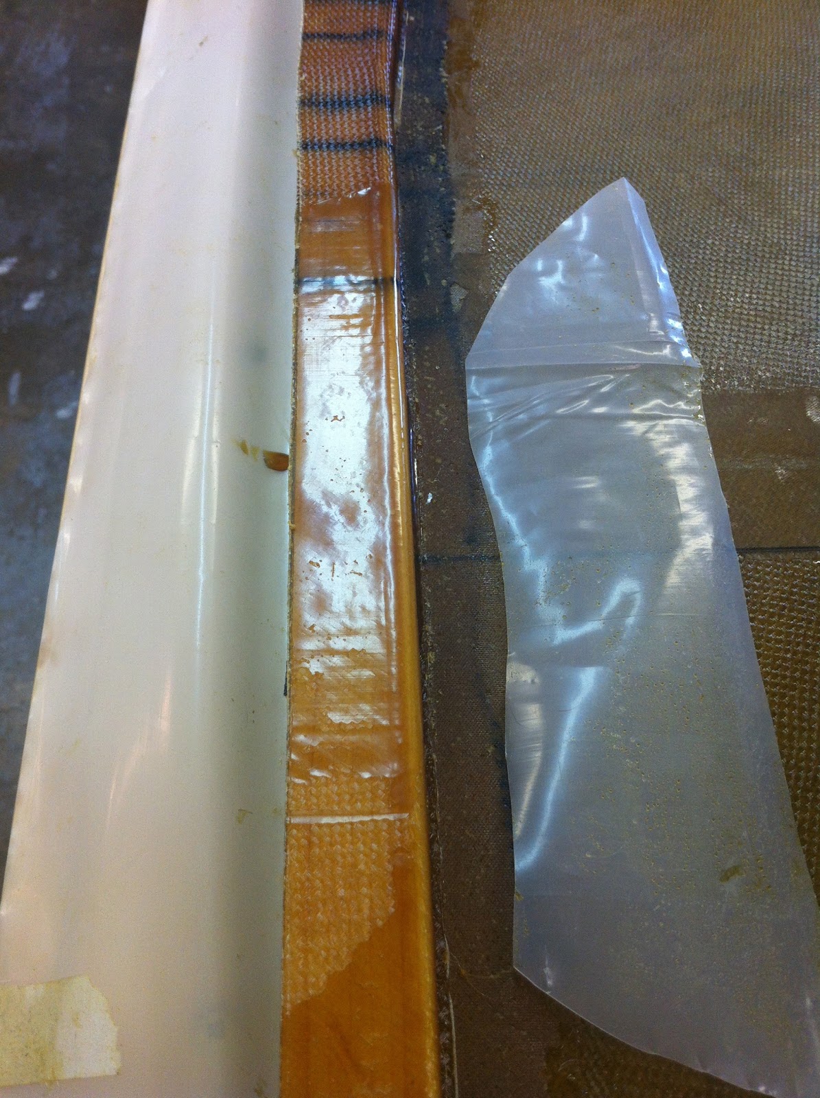
After the motivational interlude, I got busy cutting and fitting the stringer, basically the other half side of the rear lower longeron. 


I used plenty of wet flox on the mating surfaces, since it’s easier to clean up the excess, than it is to add more later.


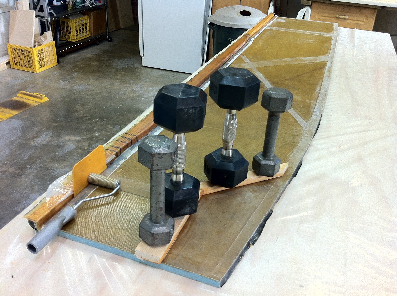
Then I threw every clamp I had at it, trying to bend it to match the other half. 
You might ask why I didn’t cut slots on the stringer as well, to help bend it. The answer would be, I’m not sure. But looking at everyone else’s photos of this step, no one else has found it necessary to do so, and the manual is mum on this technique as it applies to this part. 
Maybe cutting on the base of the triangle might weaken it too much. Again, I’m not sure, but enough force was brought to bear that it never became an issue.

Pretty much everything I've got!


With the flox curing I had nothing else to work on, so I went back to the lathe, and mill, made a test bushing out of some scrap, and pressed it in some leftover aluminum angle I had laying around.

This test piece has demonstrated counterboring (top hole), and now press fit steel bushing.

The reason I am even experimenting with this, is that in CP #46 (Builder Hints), Burt states (talking about the landing gear extrusion in LMGA assembly): “ ... if you bought your extrusions from Brock, you will note that they have flanged, steel bushings pressed into the aluminum angles, these steel bushings ... are an excellent idea.” 
Unfortunately he gives no dimensions at all, so I am polling all my builder friends, and trying to come up with some I can use.

UPDATE: Wade just phoned in with some dimensions he called “exact”. In reality he probably made them up to shut me up, but I’ll try them on for size next time around anyway.


Ch. 5 - Fuselage sides LH - Part 2


Lower longeron (6.7 hrs)
The good news is that the air bubble I was chasing last night is gone.

Bubble-less surface

Unfortunately the bad news is that another bubble appeared somewhere else, and I’ll have to "terminate her".

No, it's not a snake!

Since I did not use any flox to radius the 90˚ angle above, I was almost expecting air bubbles to appear at the intersection with the foam board. I’m actually surprised I did not get any more than that. In retrospect I should have eased the transition, and I definitely will when I make the right side-panel.
To correct this issue, I had to drill two holes at either side of the bubble, and inject some epoxy with a syringe I "borrowed" at my last dental appointment.


I was told this should work, but I had never actually done it before.


Wow, that was awesome! I will definitely use this technique again next time I screw up.


By the way, I ended up drilling another hole further to the left, and filling the remaining void with epoxy.


One additional item I had to take care of, was the removal of BID I had laid on the last 0.5” of the longeron. Apparently it wasn’t supposed to go that far, so I took a razor knife and cut it off. Simple enough.

BID extending all the way to the rear end of the top longeron

Removing the offender

Problem solved

The new item for the day was the lower longeron. I drilled holes through it, and the cured fiberglass, and inserted some nails to hold the wood in place. 

Working on the lower longeron

Because the longeron needed to curve upward in the aft section of the fuselage, I cut some slots on the top side of the longeron, to aid in achieving the proper curvature.

Slotted longeron temporarily in place.


"Nice curves!"

After dry fitting, I mixed some wet flox, applied it to the longeron’s back side, and put it back in position.

Applying wet flox while "enjoying" the hot and humid midday
A substantial amount of weight is useful to hold the longeron down while the flox cures, but its sharp edge makes it challenging to weight it down without damage. Since I am not that smart, I will admit to shamelessly plagiarize the following “load distribution scheme”.

I wish I could take credit for this idea

Basically it consists of a grove cut into some scrap lumber, matching the triangular profile of the longeron. This was easily accomplished with the table saw, and the results were as brilliant as the individual I stole this idea from (thanks again Walter).
I was then able to pile up as much weight as I could physically fit on top, without any fear.

Plenty of weight holding things down while the flox cures


Wednesday, June 27, 2012

Ch. 5 - Fuselage sides LH - Part 1


Glassing the left fuselage side (11.0 hrs)

Wow, was that a BIG job! 
Well, at least the biggest so far. 
This baby gulped epoxy faster than I could mix it! 
But, let’s back up a few hours... starting with planning the layup.

Planning the UNI cuts


It turns out that just two pieces of UNI are enough to cover the whole side-panel. Multiply that by two, since the layup requires two plies.
To cut down on the mess, I borrowed my friend’s Wade idea of masking the edges with duct tape. That worked very well, as there was a lot of runoff.

Taped edges


Unfortunately I was too busy mixing epoxy, spreading it, stressing out about it getting hard before I could finish, running out, mixing some more, etc., to stop and take pictures of the process.
Really, it was the same basic idea as previous layups, actually easier since the panel was flat, but the size of it added an extra dimension (no pun intended) to the process.
After I finished glassing, I mixed some flox, buttered up the longeron, and pressed it in place, then added some weights to it, and let it rest overnight. 
Before shutting down for the night, I peel-plied everywhere I thought I might need to later attach anything.

Longeron in place


Back in the house, looking at Walter’s pictures, I realized I forgot to peel-ply in front of where the spar will go. So, I went back in the shop while the work was still wet, and quickly added some.

There's always one...


That was a good save!
For some reason, seeing the black lines I had drawn on the foam through the fiberglass, was more difficult than usual. Since I was getting tired, and was having a hard time determining where LWX and LWY (wood pieces) should go, I peel-plied the whole back section, and “lived to fight another day”.
The next day I removed the peel-ply, and spent the rest of the morning picking at the peel-ply strands that did not come off, using razor blades, scribes, sandpaper and such. 
What a colossal waste of time that was!
I’m starting to hate the quality of this peel-ply, since the time I should be saving by not sanding, I am instead using trying to remove little elusive and embedded peel-ply strands.

Inner left side of fuselage


The next thing to do was to redesign the whole gear mount geometry back there. That took quite sometime, as it did the first time, but it eventually came together, and I marked the positions on the hardened fiberglass.

Head scratching time


One last trial fitting session was in order before committing to flox.

Looks good to me!


Finally satisfied, I floxed LWX and LWY in position, and put some weights on them.

LWY with flox


LWY in position


Working on the opposite side of the side-wall, I was able to knock out another item, the glassing of the longeron. This consists of 3 plies of UNI (0˚) covering the stiffener area, and 1 ply of BID (45˚) covering the whole longeron, including the aforementioned UNI plies.


Cutting BID strip at 45˚


Glassing the longeron


All in all, not a difficult job, but I eventually got into a struggle for supremacy with an air bubble, and spent quite a considerable amount of time, and brain cells, figuring out how to squash it. 
I am still not sure if it is gone or not. I guess I’ll find out in the morning.
So, here's how far I’ve come in the past two days.

Done for the day


Barring any other slowdowns, tomorrow I’ll be working on the bottom longeron.


Monday, June 25, 2012

Ch. 5 - Longerons

Smooth transition (0.5 hrs)


In “Epoxy 101” I discussed the fact that fiberglass does not like making 90˚ transitions. 

When rounding an inside corner we must lay down a fillet to ease the transition, usually made of dry-micro, but sometimes flox as well, depending on the situation.

Covering an outside corner with fiberglass, we have to round the corner for the same reason, but we use a different radius depending on whether the glass fibers run perpendicularly, or diagonally across the edge.

Plans directions

In the case of the longerons, the plan calls for BID laid at a 45˚ angle, so a 1/8th radius of rounding should be sufficient to allow the fiberglass to lay smoothly around the corner.
Naturally, one could easily eyeball this, and take a sanding block to the inner/lower edge of the longeron, and “go to town” with it. But why go through all that trouble, when one could just as well acquire a rounding bit, pop it in a router, and perform the same action at 10 times the cost?
That’s what I thought! Something about power tools...
So, here’s the more expensive, though easier way of getting the job done.


The result is at the very least consistent throughout the 103” length of the longeron.

Longerons ready to go


Epoxy 102


Un-Gelling the hardener
Before I left for my latest trip, I ran into a problem when I tried to use the E-Z Poxy hardener. It had turned into a big lump of Jell-O, and was basically unusable. 

Looking into the hardener canister

This had me a little concerned since this stuff is not cheap, and it's only 4 months old. 

I had read that this might happen if the container is kept in a cold environment, but this year we have had an unusually warm winter, and my shop never got below 50℉ (10℃), nevertheless... there IT was.
Tracy, at Aircraft Spruce, hinted that heating up the hardener to 120℉ (49℃) would probably return it to usable conditions. 
Still skeptical, and expecting the worst, I decided to give it a try with a small scale test on the little container I employ for ratio testing, itself afflicted by this apparently infectious condition.

Coagulated hardener

You can see the video I took of this experiment below.


UPDATE #1:

I heated up the canister of hardener to 120℉ as directed, and it worked beautifully.


Heating up the hardener to 120℉

Compare the way it looked in the pictures above, to the way it looks now.


UPDATE #2:

CP 29 page 5 states that this temperature should have been between 160℉ to 190℉  (71℃ to 88℃). 

Check out Epoxy 103 for more details


UPDATE #3:

Apparently the resin can crystallize as well. 


Resin solidifying

Solidified resin (later melted back with heat)


Just follow the procedure highlighted above.