Chronicling my Long EZ construction (and a few other things).
Disclaimer
This blog is for entertainment purposes only, and is not meant to teach you how to build anything. The author is not responsible for any accident, injury, or loss that occurs as a result of reading this blog. Read this blog at your own risk.
The small landing gear brackets (front) have to go through the same process as the big ones (rear) did. Basically, drill the mounting holes undersize, ream them to the proper diameter, mill the lightening holes, and sand it all to shape.
The paper templates proved themselves to be quite precise, and the holes I have drilled so far have ended up with the correct placement.
Front-right landing gear bracket lined up behind rear bracket .
Front-left landing gear bracket lined up behind rear bracket.
In spite of this, I decided to use the templates just for initial positioning, and employ the actual brackets for proper alignment of the holes instead. This way any error in the rear brackets would get duplicated onto the front one, guaranteeing parallelism between the LMGA tubes, and the fuselage sides.
I used the table to make sure the brackets lied onto the same plane, and once the hole and the template lined up, I clamped them together.
Immobilizing brackets before drilling.
I then mounted them on the mill vise, and spent some time leveling them precisely, so that the holes would turn out perpendicular to the surface.
Leveling brackets with the help of a dial gauge.
I used the 1/4” reamer fitted to the mill head, to line up with the hole in the rear bracket (the one on top). Then I removed the reamer, and the rear bracket, and used a series of increasing drill bits to bring the hole to 7/32” (5.55 mm). Finally, I enlarged the hole with the 1/4” (6.25 mm) reamer.
Reamer lined up and ready to roll.
If you have never used a reamer before, here’s a short clip of myself reaming one bolt hole. As you’ll see, it’s pretty similar to drilling a hole, except that you need a hole already made to begin with, and you do not want to run the bit in reverse or you’ll risk damaging it. These reamers are pretty delicate tools.
I used this same technique for all the mounting holes, as well as for the lightening cutout.
Aligning 3/4" end mill.
Here’s a video of the milling of the lightening hole. I decided to add it because it’s pretty wild, with lot metal chips twirling about, but it’s also 4 minutes long, so watch it if you’re into that kind of stuff.
Later, I bolted the two front brackets together, and sanded them to shape. Here they are after sanding.
Completed left and right front brackets.
Finally, I was able to put all of the pieces that will attach to the rear, inner fuselage skin, together to form the main landing gear attachment points. Here are a few pictures of the finished product.
Complete right assembly.
I used some bolts to join them loosely, to see if the holes would line up. Given all the variables involved, and the cumulative small errors, it’s kind of scary how precisely they mirrored each other.
I had already roughly cut the landing gear brackets, so today I sanded the big ones smooth, and drilled all the holes required in the plans. I spent some time leveling the bracket in the vise, to make sure the holes would be drilled perpendicularly.
I made all the holes 1/32” (0.794 mm) undersize on purpose, then used the appropriate size reamer to enlarge the holes to the correct diameter specified in the plans. This extra step is probably not necessary, but ensures that the holes are perfectly circular, and precisely dimensioned.
About to enlarge gear mount main hole.
Reaming rudder cable pass-through hole.
After all of the mounting holes were completed, I moved on to the lightening holes. I did not have a 3/4” (19.05 mm) drill bit, but I did have two end mills in that size, one of which suitable for plunge milling.
Plunge/side cutting mill (left), and side cutting only mill (right). Note the different head profiles.
With it in the collet, I started cutting the holes in the first bracket as depicted in the paper template.
Removing weight, every ounce counts.
Before starting on the other bracket I bolted them together loosely, so I could sand them smooth, and to the same shape.
Evening things out.
Instead of relying on the paper template glued onto the second bracket, I aligned the uncut bracket with the previous one using bolts. I used this set up to position the cutting tool, thereby guaranteeing the symmetry of the pattern.
Lining up the end mill.
I am pretty satisfied with the way they turned out, see for yourself below.
This is going to be the "mother of all posts", I apologize in advance for its length and subject, hopefully this will be my last one discussing the lathe modification, and I will go back to making airplane parts soon.
Because it might be of interest to mechanically minded people, of which pilots make up a high percentage, I decided to include it in the blog, even though it does not strictly address airplane building.
In “Tooling up” - Part 4, I diagnosed the lathe’s tooth skipping and hesitation problems as a less-than-full contact between the rack and pinion of the automatic feed assembly. Replacing the pinion has had no effect, but disassembling the lathe has revealed further evidence in support of my theory.
Apparently, during the painting process in China, red overspray had made its way onto the rack, and usage of the machine has worn down this coating enough to reveal the true extent of the rack and pinion interactions.
As you will see in the pictures below, only the very tips of the rack gear are devoid of paint, showing shiny metal only where contact has occurred with the pinion. The deeper part of the grooves still shows much red paint, evidence that no contact between gears has been taking place there.
Showing superficial wear in the rack
Red paint still in the deep part of the grooves
To confirm this finding I decided to reassemble the lathe and try to take a short video of the mechanism in action. This was very difficult to do because there is only enough space to stick my iPhone in sideways, or the flashlight, but not both. Furthermore, it also had to be done with one hand, since my other hand was needed to turn the manual feed wheel back and forth. It took several tries, dropping one or the other, but I was eventually able to get a clear video detailing the lack of contact between gears (you might want to see this full size on YouTube).
I think you will agree that there is still much rack gear space above the pinion that goes unused, and I have come to believe that full engagement is necessary for proper smooth travel of the “saddle” (to be identified next).
Because the automatic drive case, aka the “apron” (#70) is joined underneath the “saddle” (#93) using two bolts (#97), it stands to reason that removing a certain amount of material off the top of the apron should raise it, as well as raising the pinion (#81) attached to it.
I estimated the amount of steel to remove with the mill to be 45/1000”, or 1.143 mm.
Apron, with pinion gear (the one sticking out) before going on the much needed diet.
Starting with a perfectly leveled apron held in a vise is critical for this operation, so only the desired amount of material will be removed.
Using a dial indicator attached to the mill tower, I carefully leveled the top surface of the apron. In the video below you can see how I checked for level. The video is shaking a bit because my right hand is cranking the hand-wheel, while the left hand is shooting the video.
With everything ready to go, the only thing left to do was to start cutting. Now, this was the first cut I ever made on anything with a mill, so I was pretty nervous. I made a number of light passes back and forth until the correct depth of cut was reached (0.045” or 1.143 mm).
To make sure I wouldn’t cut anymore than I had decided on, I mounted the dial indicator on the mill column pointing up, so that it would contact the movable head of the mill, then set it to zero. As I lowered the head of the mill after each pass, this height change read on the indicator.
Final depth of cut (45/1000") reached.
This is what the apron looked like after the final pass.
After a light buffing it looked very smooth.
Apron not connected to the saddle yet.
I loosely installed it back in the lathe temporarily, at roughly the original height, to give an idea of the amount of material I removed from the top of the apron.
Apron in place with loose bolts.
Once the bolts were tightened up, the rack an pinion made perfect contact :-), as they were designed to do. The manual feed is now smooth and immediate, with no hesitation, and should help produce better parts, with more consistent finish.
This fairy tale would be just that, if it weren't for one little detail I neglected to consider. :-(
You see, now that the apron and all its attached components are 45/1000” higher, so is the “half-nut” (#75). While this is not a problem in its opened position (manual feed), it very much is in its closed position (automatic feed), as the half-nut tries to clamp on a lead screw that is now 45/1000” lower.
Looking at the last photo, you can imagine how raising the apron would cause the half-nut to actually raise and bend the lead screw upward. In the next video you'll actually be able to see this bending taking place.
This is bad enough when in the middle of the lead screw, but it would create some serious issues at either end of it, where the screw it is bolted to the bed and unable to flex upward. So, we've got ourself another problem to solve, and this one is going to be a doozy.
You might want to take a breather here.
...
Here we go!
To think this problem through, it's necessary to visualize the mechanism that drives the half-nut to open or close.
The half-nut is a two piece device (quarter-nuts, perhaps?), these have one pin each (#74) on their back, which ride in separate slots on a "groove cam", that drive opening and closing of the half-nut.
Half-nut in open position (manual saddle feed)
Half-nut in closed position (automatic saddle feed, with lead screw rotation)
Half-nut in open position (notice orientation of the slots)
Half-nut in closed position (notice horizontal orientation of the slots)
The part bearing the grooves is the “groove cam” (#78), and has a handle (#79) on the apron side that allows it to rotate between the two positions.
The length and shape of the grooves determine when, and by how much the half-nut will split, and where it will start and stop its travel.
Groove cam opens or closes the half-nut through a handle that attaches where my fingers are.
The critical position is obviously the closed one, because positive and precise engagement of the lead screw is required. As far as the pins are concerned, the open position can happen anywhere along the slots, as long as the half-nut disengages the lead screw, and so it’s a little more flexible position.
Because the pins ride up and down in the middle of the apron’s channel, aligned with a vertical line passing through the center of the groove cam, the inner part of the slots will have to be moved downward to lower the half-nut when in the closed position.
Required downward translation of the inner part of the slots.
These parallel slots will then become diagonals, but there is one more twist. The locking mechanics of this arrangement requires a horizontal run of the slots, to assure that the pins will be stable once in the closed position, but the modification creates an unstable diagonal setup instead, prone to uncommanded opening.
Theoretically at least, this diagonal should really be an arc, to neutralize side forces and binding as the pins move vertically while the cam rotates. In the video, A is the closed position, and B is the open position of the perfect top slot, after rotatingthe engagement lever (represented by my fingers)45˚. Note that the marker is moving in a straight line forward, as the cam rotates beneath.
Good luck milling that!
My solution is then to mill 3/4 of the slot diagonally, followed by a short horizontal run to ensure positive latching in the closed position.
Exaggerated view of new vs old slots
Obviously the original groove cam cannot be reused, so the first step is to create a blank one on which to mill the reengineered slots.
And so it is that the lathe (with some help from the mill) will create the very part necessary to heal itself, and it all started with a piece of raw steel.
Steel bar graciously supplied by Gene LaDue, who owns a very cool machine shop (the real deal!)
I worked it on the lathe until I produced this blank.
Chinese grove cam on left, Italian on right.
Then again, since I made it on a Chinese lathe, maybe it is Chinese also.
I used a black marker on the original groove cam, and transferred an impression of it onto paper. Using tracing paper, I copied the dimension of the grooves, then modified as I described above. I didn't want to have to redo this step again if I ruined the paper, so I made a photocopy of it, and checked it for stretching.
Armed with my new template, I glued it to the steel blank I had produced.
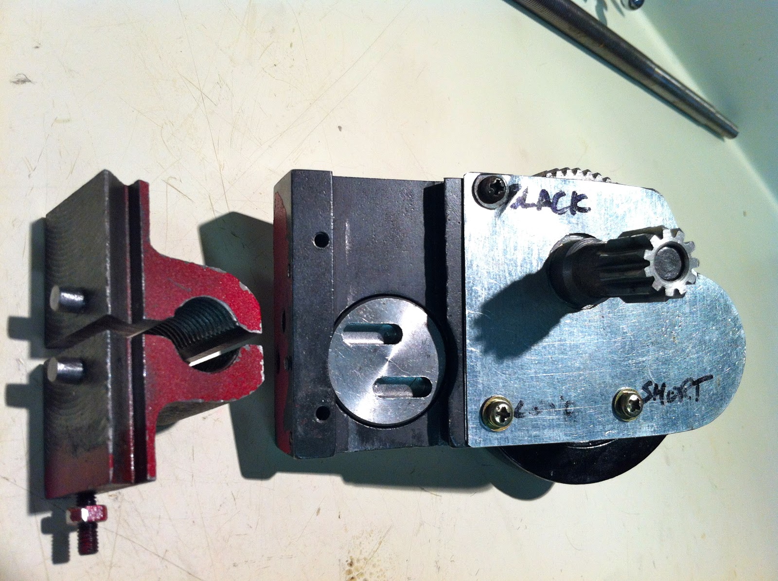
Now, before I could start hacking away at it with the mill, I had to figure out a way to hang on to it first. Off-axis milling forces could be high enough to rotate the part, ruining it. So light cuts and a solid anchoring device were necessary. Looking in my scrap bucket I found a piece of aluminum that fit the bill. I drilled a hole through it, then used the band saw to cut a slit through its middle.
Once in the vise, the shaft was pinched tight enough to prevent any rotation while the milling took place.
A quick change into a 5C collet and an 3/16" end-mill, and we were in business.
Aligning the end-mill.
I estimated the tool travel for the horizontal portion of the slot, to be at least the radius of the half-nut pin. Since this is a 3/16" tool, half would be 3/32" or 0.09375". For ease of reading on the dial indicator I used 94/1000".
I took a number of passes until the depth reached 0.200", then repeated the process for the second horizontal pocket.
After a quick realignment I started on the diagonal part of the slots.
Soon enough I had my modified gear cam finished.
Here it is, next to the original...
... and in its final position...
This modification, while very involved, turned out to be a great success. As you will see next, the half nut can now clamp onto the lead screw without bending it, and there still is a positive bottom latching action for the lever, thanks to the short horizontal part of the slots.
Finally, I'd like to show you what all this work has been for, a smooth, positive, lag free drive of the saddle along the bed of the lathe, with no tooth skipping even at the fastest speed. Over and out! Enjoy.