Disclaimer

This blog is for entertainment purposes only, and is not meant to teach you how to build anything. The author is not responsible for any accident, injury, or loss that occurs as a result of reading this blog. Read this blog at your own risk.

Saturday, March 24, 2012

Ch. 5 - Landing Gear mounts - Part 1

First aluminum parts (3.2 hrs)
I suppose when you build an airplane, even a composite one, sooner or later you are bound to run into some metal parts, and today is the day I put the “warm sticky nectar” temporarily aside, for a crash course in the cold art of metal shaping.
I’d like to start out by saying that thankfully, due to the labour of love by two of the finest midwestern girls (aka “Cozy Girls”), all of the required metal components are still available for purchase more than 30 years after the Long EZ was first designed. They "Girls" are indeed the best source of Canard metal parts that I know of, and their products are literally works of art. On the other hand, purchasing all of what they offer will set you back a good $3000, saving you a huge amount of time, while teaching you no useful skills, except how to write checks. 
Since pride of accomplishment and learning new skills score higher in my book than time of completion, I decided to give the manufacturing of these parts a fair try. Time will tell how wise a decision that was.

First in the line up are the main landing gear mounts.


This is what I am trying to accomplish (picture from my friend Walter's archive)

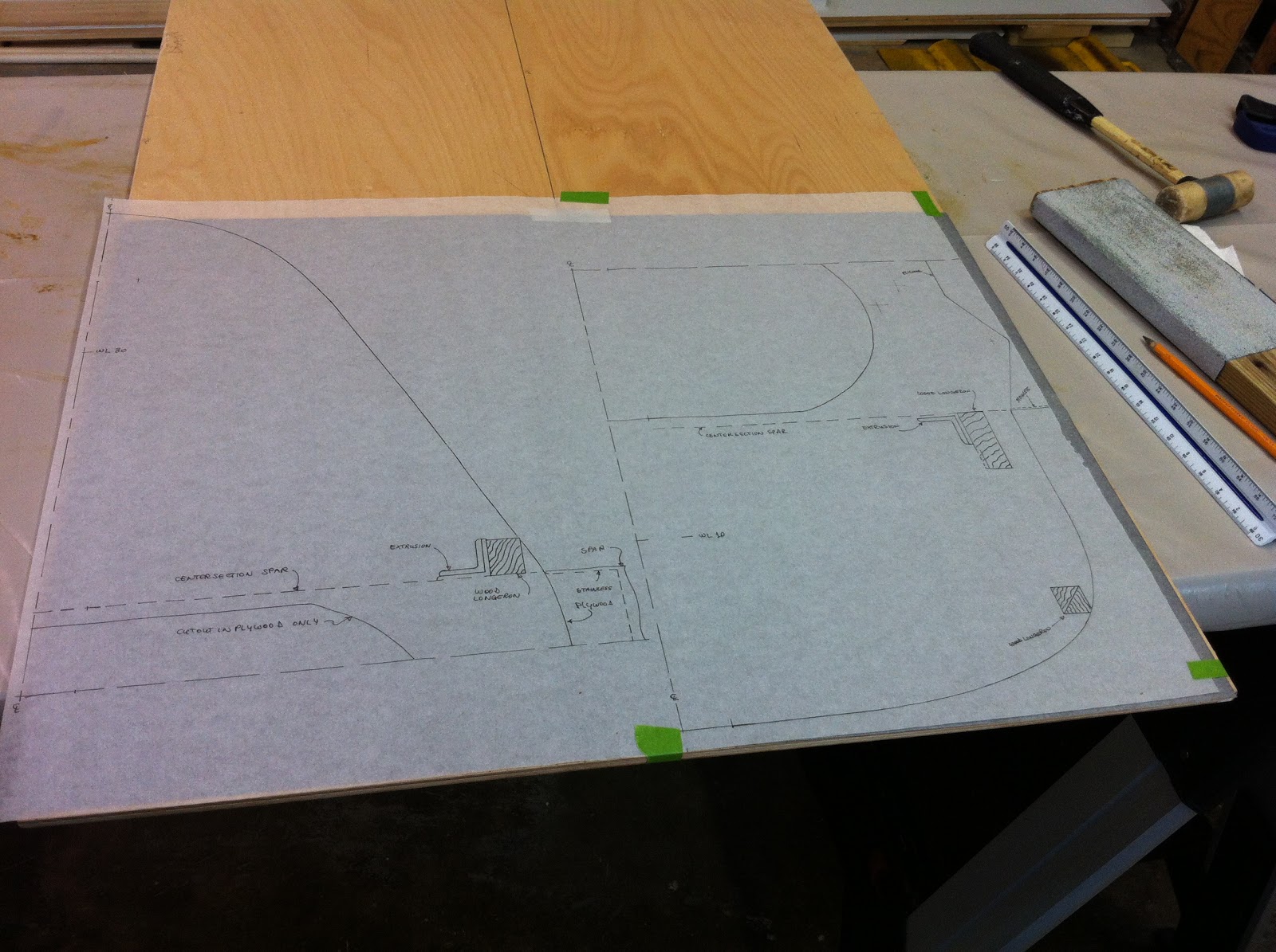
I started by tracing the full scale patterns onto the usual tracing paper, and applying to them plan change #45. This optional change appeared in Canard Pusher #27, and affects the Long EZ manual page 9-3 (although we are working on chapter 5, the actual drawing and dimension of the main landing gear mounts are given in chapter 9).
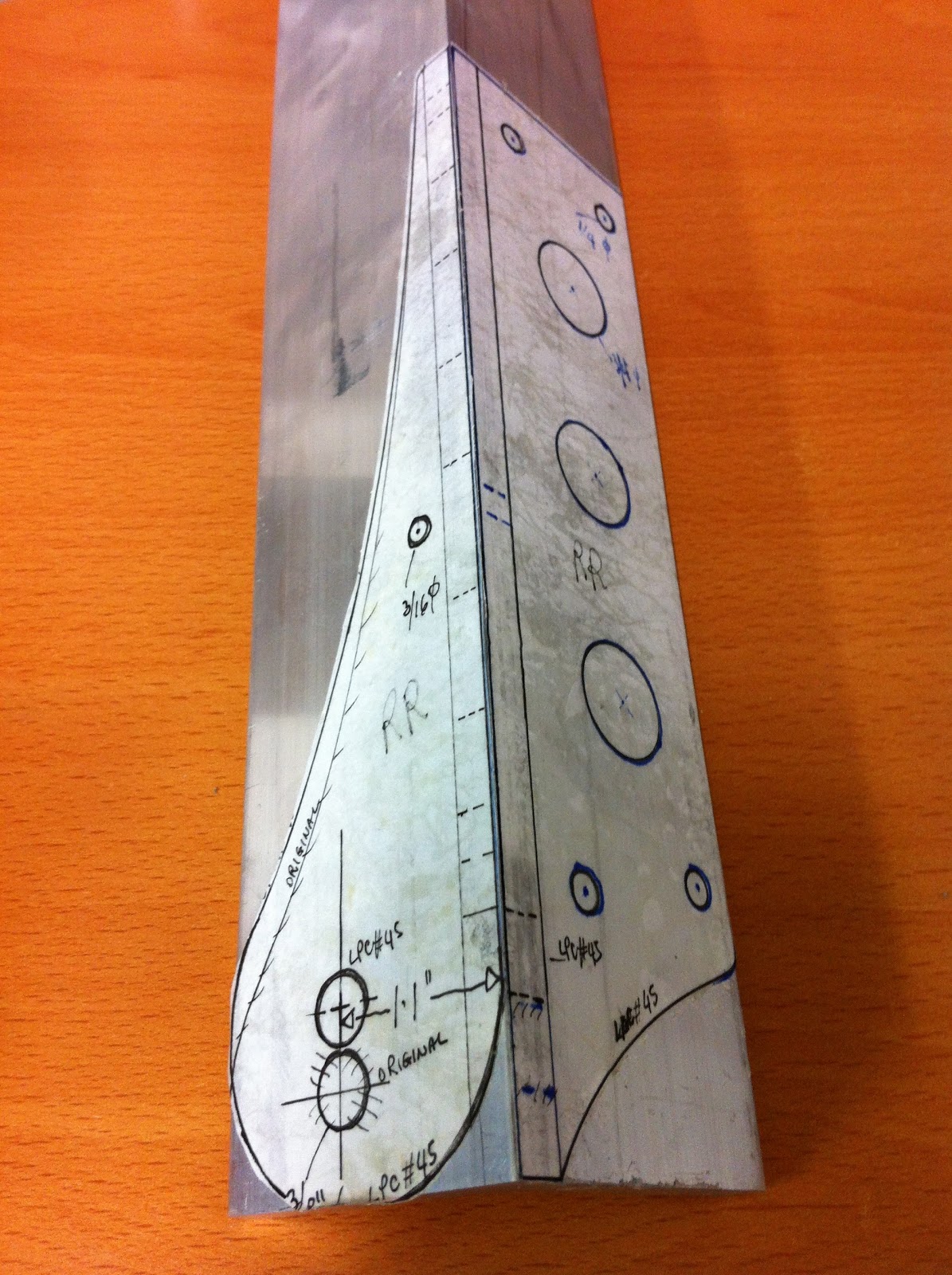
LPC #45 directs us to: Move the 3/8" holes in all four extrusions up 0.4". Also modify outlines to maintain original edge distances around the 3/8" hole. This moves the entire main gear up 0.4", resulting in an improved gear-fuselage juncture reducing aerodynamic drag.

Main landing gear rear mount (LPC #45 applied over original drawing)

Main landing gear front mount (LPC #45 applied over original drawing)


Once again the manual only gives us the drawings for one side of the plane, and it’s up to us to draw the mirror image for the other side. This is done simply enough by folding the tracing paper over onto itself, and tracing the drawings one more time.

Tracing the modified drawings

Two sets of gear mount drawings (one will be used flipped over)


If you have been wondering where all of this tracing is headed, hang on... I am about to try out a new idea. 

Mirror image templates ready for use


I decided to use some leftover contact adhesive (previously purchased to glue my car’s sagging headliner back onto the roof), to glue the drawings directly on to the 2” x 2” x 1/4" 6061-T6 aluminum angle. 

If I had to buy it specifically for this task, I wouldn't get the Hi-Strength kind


I figured this would allow me to easily locate all the features to be cut, or drilled. How precise this would turn out to be, I was still not too sure of, but I was willing to sacrifice the $9.00 aluminum extrusion to find out.

Drawings glued to aluminum angle


With the pieces of papers stuck onto the aluminum, I was ready to start cutting with my new modified portable saw. 

Portable metal cutting saw inserted into custom saw table from SWAGoffroad.com


While I’m planning on discussing this saw in a future post, I’ll just say here that it worked very well.

My first cut. I'm feeling some "separation" anxiety?


All 4 pieces were separated in a short time.

Basic raw material


Next, I took the saw back to the individual pieces to trim them down further.

Getting more daring with the saw

Treading ever closer to the black line!


A short while later I had all 4 pieces rough cut, and ready for some more precise trimming.

Still rough, but already looking the part.


Because I was afraid of what the glue might do to the paper, like shrinking it or blurring the ink lines, I went ahead and center-punched all the hole centers before going to bed. This way I figured, even if I totally lost the paper, I would still have enough features to complete the work.

Precision center punching before going to bed... not the smartest idea.


As it turned, out I shouldn’t have worried, because the next morning everything was still exactly as I had left it.
In spite of this small measure of success, my good friend Walter brought up a valid question about the precision of such a method of locating features on the metal. 
So, I took a caliper to the parts to measure their most important dimension, the 1.1” distance between the edge of the angle, and the center of the gear mounting hole.
I was pleasantly surprised to find out just how tight the tolerances were.
I’ll let you be the judge.

1.1 inches... check!

1.1 inches... check again!

1.1 inches... Are we there yet? ... Check!

Low blow (with the center punch)... 1.1 inches... CheckMate! 


I think I’ll use this method again!


UPDATE

Looking back at this post from chapter 9, I think if I were to do it again, I would omit LPC #45 altogether, since the 2" (5 cm) wider fuselage already raises the gear bow by 0.4" (1 cm).


Tuesday, March 13, 2012

Ch. 4 - Instrument panel - Part 4

Cutting holes in the Instrument panel (3.1 hrs)
I’ve been wanting to cut the instrument panel for some time, but I worried about cutting tight radii (radiuses) with my vibrating cutter. I finally could wait no longer and started cutting anyway. 

Throwing caution to the wind


The tool produced a cut all right - but not the clean one I had hoped for, and for every rough cut I made, I could just imagine hours spent sanding fiberglass.
Nevertheless, I cut the two main leg holes, and tried sanding them with this drum attachment on my cordless drill.


That did not work!

Needing a better idea


Even at its highest speed the drill was too slow to remove any material, and because of that I had to use a lot of side pressure against the piece to force feed the sandpaper. Still not much was happening, except for my arm getting tired of holding the heavy drill.
Time to change strategy, and... when the going gets tough... the tough go shopping!
A trip to Home Depot rewarded me with a much sought after Dremel attachment. And this baby can make 90˚ turns!!!

Practicing on some scrap


While it looks like an innocuous drill bit, it is instead some sort of monster milling device that plunges into the work with the tip and cuts with the sharp sides. It is rated for a number of hard materials, including fiberglass.
Scored!

Tracing the hole


With the bit spinning at 5000 rpm you have to hang on for dear life to the tool, with both hands. 

Finished cut undisturbed...


Kind of dangerous really, but man... it cuts like a hot knife though butter!

... and disturbed :-)


It also allows you to cut right up close to your line, minimizing the sanding chores.

Pretty good finish for a roughing pass


It is so good in-fact, that I went back and trimmed the leg holes I had previously cut.

Panel cut, before sanding


While at the store, I also purchased a drum sanding attachment for my Dremel tool. Once spinning at 5000 rpm this bad-boy removed enough material in one pass as 1 hour worth of hand sanding.
Love it!

This was Mike's idea, and a good one I'll add.


Before long the instrument panel was completely cut and sanded...

Done! Finito!


... and this left enough time for a photo op...

"Experimental 123... you are cleared for take off!"


Ch. 4 - Firewall - Part 1

Cutting the firewall (7.5 hrs)
There is an important decision that I have been putting off for a long time.  But the time has come to make up my mind, because the firewall lay-out demands it.
Not surprisingly, my choice of widening the fuselage by 2” all the way to the back seat, ended up altering the relationship between the longerons (attached to the fuselage sides), and the engine mount.
The wooden longerons connect to the steel engine mount by way of aluminum extrusions. The bottom line is that all three must line up, or there’s a problem.


This junction is complex to say the least. Here, a steel engine mount attaches to an aluminum extrusion, that is bolted to a wooden longeron, that is embedded in fiberglass, that is epoxied to a piece of foam. There is some poetry about it, don't you think?
Mike Beasley's plane


Anyways, the two options are to either keep the longerons relation to the fuselage sides, and end up 2” wider at the engine mounts (1" each side), or to double up the longerons behind the back seat, and exit through the firewall in the original position, ready to match up with the standard engine mount.
Either options present disadvantages of some sort.
The first option would be desirable because it wouldn’t change the way the fuselage is put together, with the exception of some metal tabs in the wing spar that would have to be moved further out. The downside is that it would require a custom engine mount ($$$).
The second option would retain the standard engine mount, but require some major modifications to the fiberglass layup schedule, and also introduce a twisting moment on all the bolts connecting the aluminum extrusions to the longerons.
After going back and forth on this issue for the past 6 months, I decided that I could not accurately predict the long term effects of these twisting loads on the structure, and that it might become a source of concern later in the life of the plane. I decided that some kind of modification to the engine mount would be a stronger and more reliable option; furthermore it would keep the longitudinal forces lined up with the longerons, as per the original design. 
With the big question sorted out, I set out to design the firewall, by basically adding 2” to the middle of it, while pushing all items on the drawing to the sides. Another change I am incorporating at this juncture, is making the firewall 3” taller. This will create more head room in the back seat, for a less cramped experience. Should I change my mind later on I can always trim it down a bit, so this choice was a no-brainer.
Like the F22 drawing, the firewall drawing shows only the right side of it, and you are required to make both sides. In addition, it is divided into top and bottom, so you’ve got yourself a little puzzle to modify and reconnect.

Modified drawings ready to be traced onto the plywood


Luckily, the plywood sheet I had purchased allowed for enough room to grow, and with some carbon paper I set out to trace my enlarged firewall.

Bottom half getting done


When I was done I used a saber saw to carefully remove the firewall from the sheet of plywood, leaving enough margin to account for the jagged edge that such a tool produced.

Firewall rough cut


I used a belt sander to quickly and accurately bring the firewall down to the proper size.

Sanding to exact size


The inner hole is for lightening purposes, and was accomplished in a similar manner.

Completed firewall


Friday, March 09, 2012

Ch. 4 - F28 - Part 2

F28 glassing - back side (0.9 hrs)
Because my F28 is 2” wider than plans, I decided to stiffen it slightly, by adding one ply of Kevlar embedded within the fiberglass. 


Cutting Kevlar with scissors takes a long time, and sanding it leaves long ragged edges. 


I used a piece small enough that it did not reach the perimeter of F28, so that I would not be sanding through it later.


I finished the bulkhead up by peel-plying the back, just as I did the front.


The next morning I just ripped the peel-ply off, and trimmed it.


Completed F28


Thursday, March 08, 2012

Ch. 4 - F28 - Part 1

F28 glassing - front side (1.4 hrs)
F28 is the last foam bulkhead I had left to make. 
In “Ch. 4 - F22 - Part 2” I cut F28 out of two pieces of foam, and the time has now come to put them together.
I discussed the different uses for pure-epoxy/micro-balloons mix in “Epoxy 101. Basically, once a honey-like consistence is reached, it can be used to glue pieces of foam, enough said.
While it’s not the most exciting of subjects, I wanted to talk about it in order to highlight another crafty, though unusual technique. Simply enough, it consists of taping the back of the two sides to each other.

F28 back side


One of the benefits, is that you can now easily access the joint, confident that it will readily return back where it belongs.


Even better, the wet-micro can be placed in the gap without any mess on the backside.


Now you set the piece back on the table... 


... and clean up the excess with paper towel. 


That’s it! Glueing is done! Cleaning is done! 

Moving on to glassing.
The plastic sheet technique worked so well on F22, that I decided to use it again on F28, after slurrying.


The two plies of BID went on quickly...


Then I glassed some 3” peel-ply on top of it, and it was done.


On a different subject, here’s a toy... I mean tool... I picked up at Lowes. You can easily make sure the part is still “in the zone” without even touching it.


I just had to have it!

The next morning I peeled the tape off the back of F28...


... and trimmed and sanded the edges.